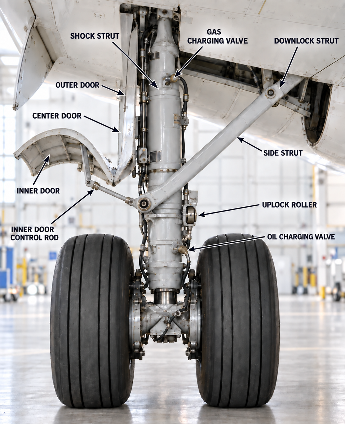
Two main landing gears and one steerable nose gear are normally extended and retracted by hydraulic system A.
Each gear has two wheels. The main gears retract inboard into open wheel wells and are held retracted by mechanical uplocks. The nose gear retracts forward, is held by an overcenter lock and is enclosed by mechanically linked doors.
Normal command
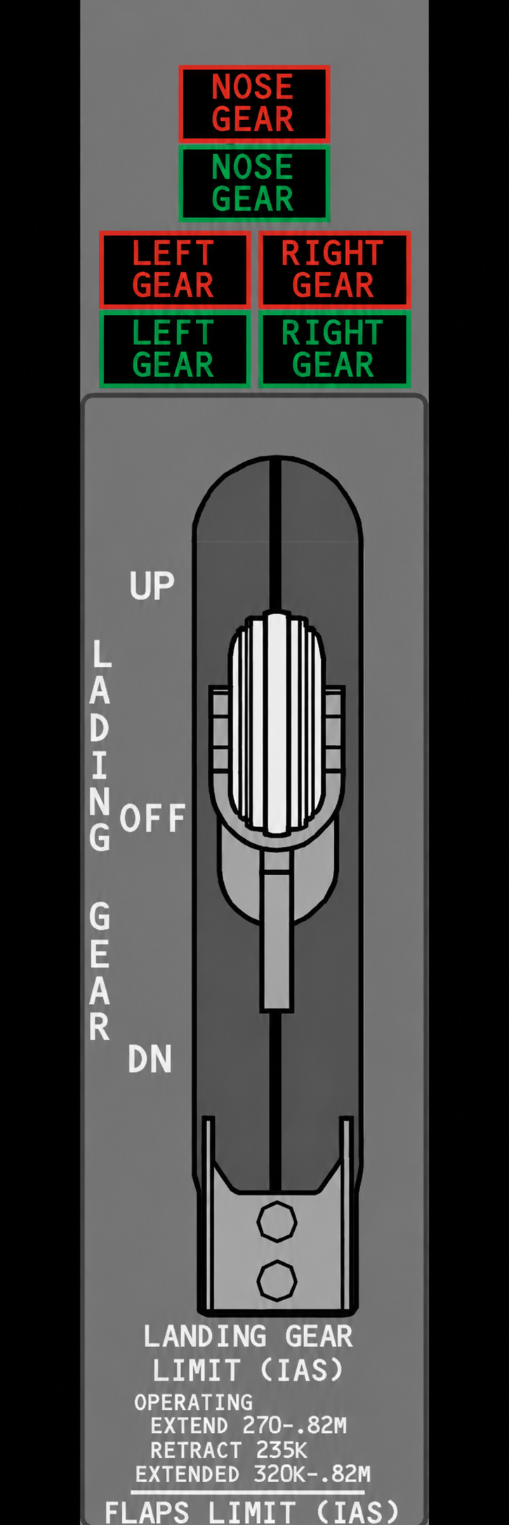
The LANDING GEAR lever controls normal extension and retraction. On the ground, an air/ground-controlled lever lock prevents selection to UP. The LOCK OVRD control releases this lock if required.
- UP: hydraulic system A retracts the gear. The main-wheel brakes stop wheel rotation during retraction, while snubbers stop the nose wheels.
- DN: hydraulic system A releases the uplocks. Hydraulic pressure, gravity and aerodynamic loads extend the gear, and overcenter mechanical and hydraulic locks hold it down.
Indication
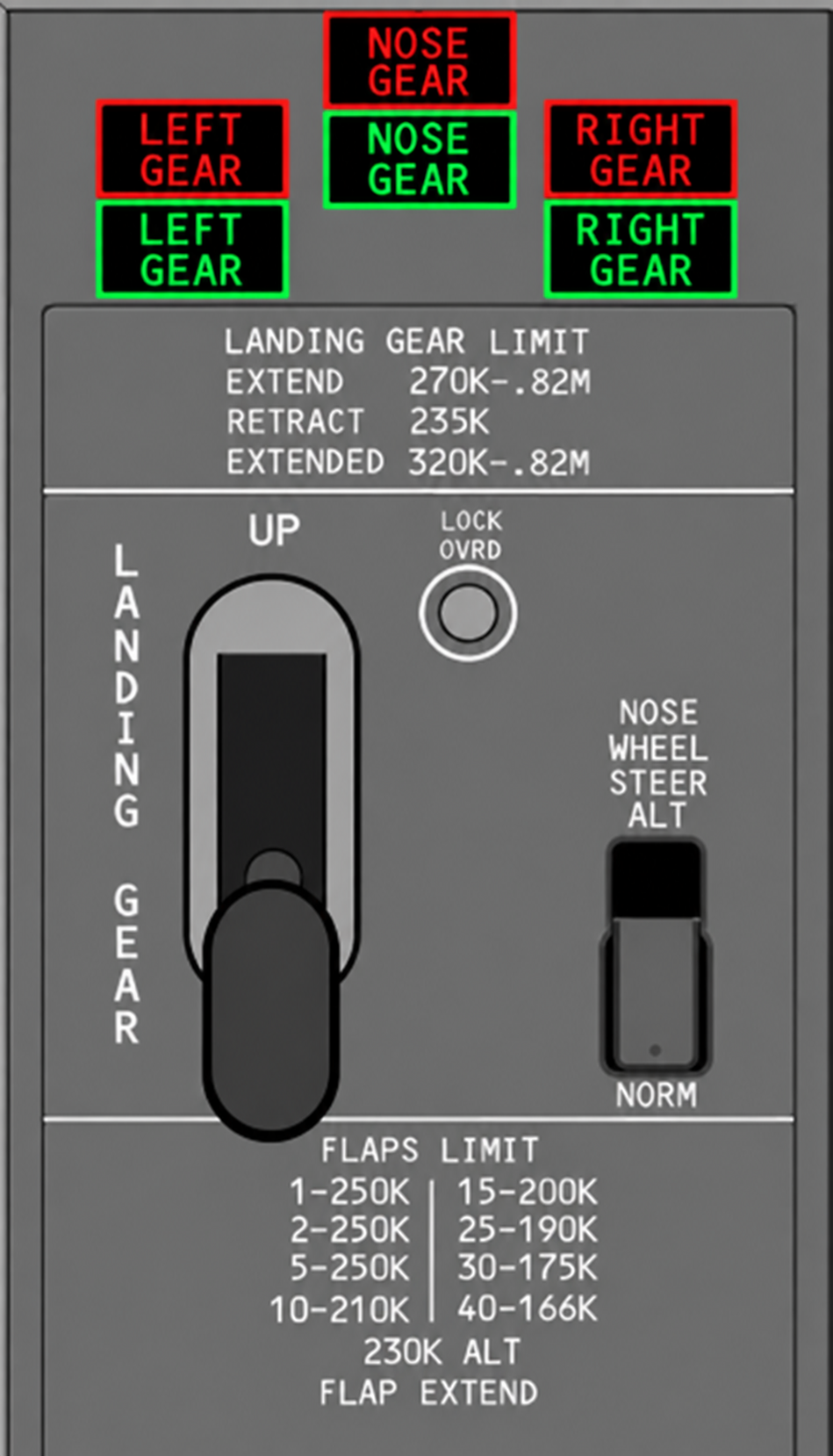
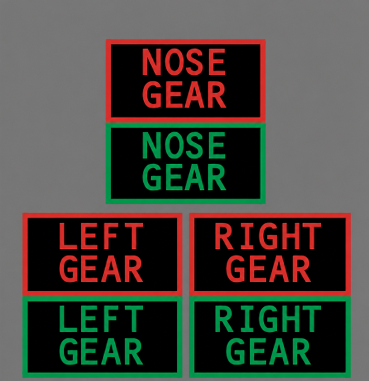
The center panel has one red transit/unsafe light and one green down-and-locked light for each gear. A separate set of three green lights on the aft overhead panel provides redundant down-and-locked indication.
- Green illuminated: the related gear is down and locked.
- Red illuminated: the related gear disagrees with lever position, is in transit or is unsafe. It also illuminates when the gear is not down and locked below 800 ft AGL with either forward thrust lever at idle.
- All lights extinguished: each gear is up and locked with the lever UP.
- Positive down indication: one green light for each gear, on either the center or overhead panel, confirms that all gears are down and locked.
Go deeper · Air/ground sensing
Six sensors, two on each landing gear, supply air/ground logic to the PSEU. The resulting ground or flight status configures several aircraft systems and controls the landing-gear lever lock.
Manual gear extension
If hydraulic system A pressure is lost, three manual handles beneath the flight deck floor release the right-main, nose and left-main uplocks through cables. Gravity and aerodynamic loads then allow each gear to free-fall to the down-and-locked position.
- Access door open: manual extension is possible with the landing-gear lever in any position.
- Normal extension remains possible: hydraulic extension can still be used if system A pressure is available.
- Retraction inhibited: opening the manual-extension access door disables landing-gear retraction.
- Handle travel: each handle is pulled fully, approximately 61 cm, to release its related uplock.
Nose-wheel steering is available on the ground with the nose strut compressed and the landing-gear lever DOWN.
Hydraulic system A normally powers the steering metering valve. Selecting ALT supplies system B pressure when the aircraft is on the ground and the system B reservoir contains a normal quantity.
- Steering wheel: primary control, turning the nose wheels up to 78° either side; it overrides rudder-pedal steering.
- Rudder pedals: limited steering up to 6° either side.
- Airborne: rudder-pedal steering is progressively removed as the nose strut extends.
- Towing bypass pin: depressurizes steering for pushback or towing without depressurizing the aircraft hydraulic systems.
Go deeper · Alternate steering protection
If a hydraulic leak downstream of the Landing Gear Transfer Unit reduces system B reservoir quantity, a sensor closes the transfer valve. This protects remaining system B fluid but causes alternate nose-wheel steering to be lost.
Each main wheel has a hydraulically powered multidisc brake; the nose wheels are not braked.
Manual brake
Pressing the top of either rudder pedal commands the corresponding left or right main-wheel brakes. The normal brake system uses hydraulic system B. If system B is low or fails, system A automatically supplies the alternate brake system.
- Normal braking: hydraulic system B with individual-wheel antiskid.
- Alternate braking: hydraulic system A with antiskid applied to wheel pairs.
- Brake accumulator: charged by system B and able to provide several brake applications or maintain the parking brake if normal and alternate pressure are lost.
- Parking brake: fully depress both pedals and pull the PARKING BRAKE lever. Depress the pedals again to release it.
Autobrake
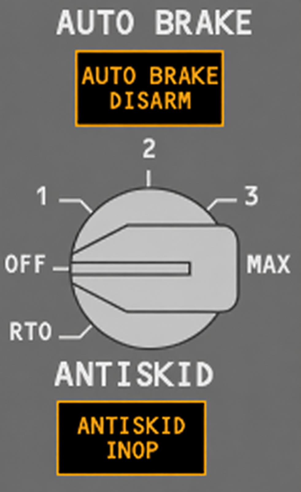
Autobrake uses hydraulic system B and operates only with the normal brake system. Antiskid protection remains active. Landing selections 1, 2, 3 and MAX command progressively higher deceleration; the system reduces brake pressure when spoilers or reverse thrust contribute to the selected total deceleration.
| Selection | Maximum brake pressure applied | Target deceleration |
|---|---|---|
| 1 | 1,250 psi | 4 ft/s² |
| 2 | 1,500 psi | 5 ft/s² |
| 3 | 2,000 psi | 7.2 ft/s² |
| MAX above 80 kt | 3,000 psi | 12 ft/s² |
| MAX below 80 kt | 3,000 psi | 14 ft/s² |
| RTO | Full pressure | Maximum, not deceleration-controlled |
- Landing arming: selecting a landing setting initiates a self-test. AUTO BRAKE DISARM illuminates if the test fails.
- Landing activation: both forward thrust levers at IDLE and main-wheel spin-up.
- After touchdown: a landing setting may be selected before decelerating through 30 kt; braking begins immediately if the activation conditions are met.
- Disarm after activation: manual braking, advancing a forward thrust lever, or moving the speed-brake lever to DOWN illuminates AUTO BRAKE DISARM.
Rejected takeoff
RTO can be selected only on the ground. A successful self-test illuminates AUTO BRAKE DISARM for one to two seconds, then extinguishes it.
- Armed: aircraft on ground, autobrake and antiskid operative, RTO selected, wheel speed below 60 kt and forward thrust levers at IDLE.
- Rejected below 88 kt: automatic braking does not activate and RTO remains armed.
- Rejected at or above 88 kt: retarding the forward thrust levers to IDLE commands maximum automatic braking.
- After liftoff: RTO disarms automatically, although the selector remains at RTO.
Anti-skid
Anti-skid monitors wheel speed and reduces brake pressure when a skid is detected. Protection is available with both normal and alternate braking, and remains available even if both hydraulic systems are lost while accumulator pressure remains.
- Skid protection: reduces pressure at a skidding wheel or wheel pair.
- Locked-wheel protection: prevents sustained wheel lock during braking.
- Touchdown protection: inhibits brake pressure until wheel spin-up confirms ground contact.
- Hydroplane protection: releases pressure when wheel-speed behavior indicates hydroplaning.
ANTISKID INOP: illuminates amber when the antiskid monitoring system detects a fault. Antiskid protection may be partially or completely unavailable depending on the failure.
The tubeless tires are nitrogen-inflated and incorporate protection against overheating and retraction damage.
- Nitrogen inflation: reduces the risk of combustion inside a hot tire.
- Pressure marking: the inflation valve should align with the lightest-point marking on the tire.
- Thermal fuse plugs: fitted to each inboard main wheel and designed to release tire pressure after excessive brake heating, reducing explosion risk.
- Brake wear indicators: two pins on each brake unit provide a direct visual check of remaining brake material.
- Maximum tire speed: 195 kt.
During retraction, the main-wheel brakes stop wheel rotation before the tires enter the wheel wells. If loose tread on a spinning tire strikes an impact fitting at the wheel-well opening, retraction of that gear stops and the gear free-falls back down. It cannot be retracted again until the fitting is reset or replaced.