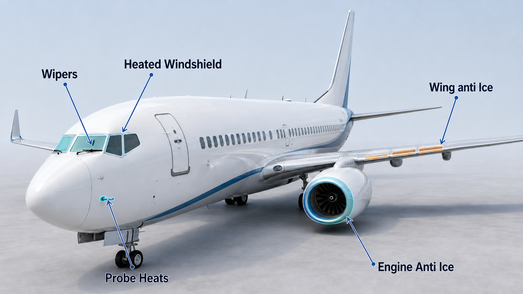
The 737 combines electrical heat, engine bleed air and mechanical rain removal to protect the surfaces and sensors needed for safe flight.
- Flight deck window heat: AC electrical heating prevents ice and fog on windows No. 1 and No. 2 and preserves their impact strength.
- Windshield wipers: independent left and right wipers remove rain from the forward windows.
- Probe and sensor heat: electrical heaters protect pitot probes, alpha vanes and the total-air-temperature probe.
- Wing anti-ice: engine bleed air heats the three inboard leading-edge slats on each wing.
- Engine anti-ice: engine bleed air protects each cowl lip; the MAX also protects the engine core automatically.
- Stall-warning logic: anti-ice use changes stick-shaker and minimum maneuver-speed margins for icing conditions.
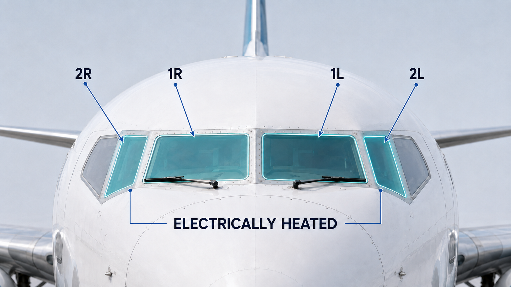
Electrical heating keeps windows No. 1 and No. 2 clear and maintains their strength for bird impact protection.
Description
Four flight deck windows are electrically heated by AC power: forward windows 1L and 1R, and side windows 2L and 2R. Windows No. 3 are not electrically heated. A conductive coating in each heated window converts electrical current into heat, preventing ice and fog while maintaining the window at the temperature required for maximum bird-impact strength.
Command
The pilot selects each FWD or SIDE WINDOW HEAT switch ON or OFF independently. Once selected ON, a temperature controller cycles electrical power automatically to maintain the correct window temperature. No manual temperature setting is required.
- FWD switches: control left and right window No. 1.
- SIDE switches: control left and right window No. 2.
- Window No. 3: not electrically heated and therefore has no WINDOW HEAT switch.
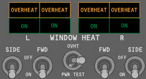

Illuminated green when heat is being applied to the selected window. It extinguishes when the switch is OFF, an overheat or system failure occurs, or the window reaches the correct temperature and the controller removes power.
The spring-loaded PWR TEST position provides a confidence test of available window heating. With the related WINDOW HEAT switches ON, it forces the controllers to full power and the associated green ON lights should illuminate. Normal temperature regulation is bypassed during the test, but overheat protection remains available. The test is intended for an extinguished ON light and should not be performed when all four ON lights are already illuminated. The OVHT position simulates an overheat condition.
Warning and indications

Illuminated amber when the related controller detects an overheat condition. It also illuminates if electrical power to the related window is interrupted. When a real overheat is detected, power to that window is removed automatically.
Go deeper · Construction and defogging
Windows No. 1 and 2 use glass panes laminated around a vinyl core. A conductive coating on the outer pane supplies the heat. Conditioned air can also be directed to windows No. 1 for defogging.
Independent left and right wipers clear the forward windows, while a permanent coating helps shed rain.
Each wiper selector has four positions: PARK, INT, LOW and HIGH.
- PARK: stops the motor and stows the blade.
- INT: one sweep cycle approximately every seven seconds.
- LOW / HIGH: continuous operation at the selected speed.
Go deeper · Permanent rain-repellent coating
Modern forward windows use a permanent hydrophobic rain-repellent coating rather than the earlier liquid rain-repellent system. The coating encourages water to bead and leave the glass in the airflow. Its effectiveness can deteriorate with wiper use, age and unsuitable cleaning methods, and maintenance can restore it using the approved process.
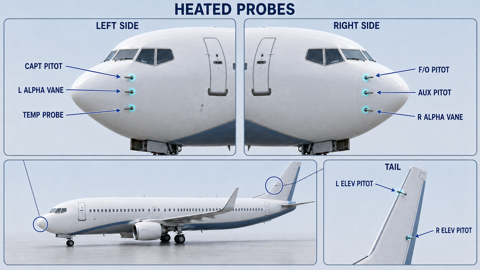
Electrical heaters prevent ice from corrupting the pressure, angle-of-attack and temperature data used by flight instruments and aircraft systems.
Description
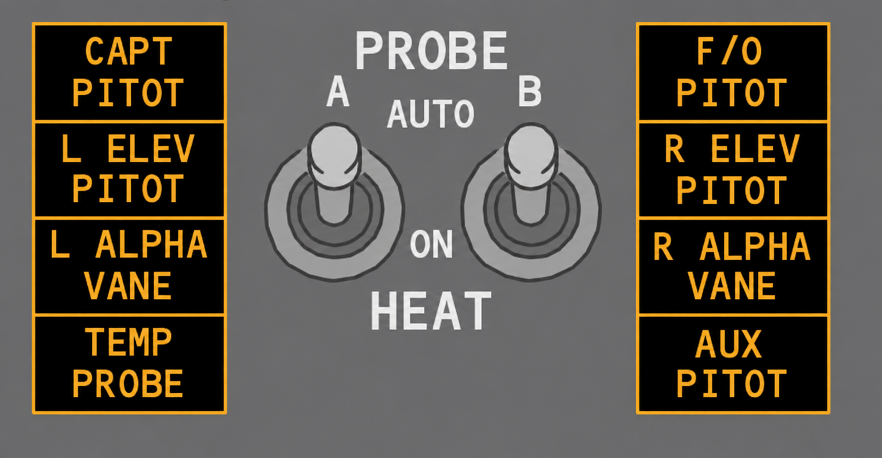
The probe heat system uses electrical heating to keep the air-data and angle-of-attack sensors free of ice. It protects the captain and first-officer pitot probes, the left and right elevator pitot probes, the auxiliary pitot probe, both alpha vanes and the total-air-temperature probe. The static ports are not heated.
Command
Two switches control probe heat systems A and B. Selecting ON supplies electrical power to the related heaters directly. On panels fitted with an AUTO position, both systems are powered automatically as soon as either engine is running; when neither engine is running, automatic heating is removed.
Warning and indications
An amber probe-heat light means that the related probe or sensor is not being heated. It identifies loss of the expected heating function rather than the presence of ice.
Go deeper · Panel effectivity
NG aircraft may have OFF/ON or AUTO/ON panels depending on effectivity. Always identify the installed switch positions before applying a memorized flow.
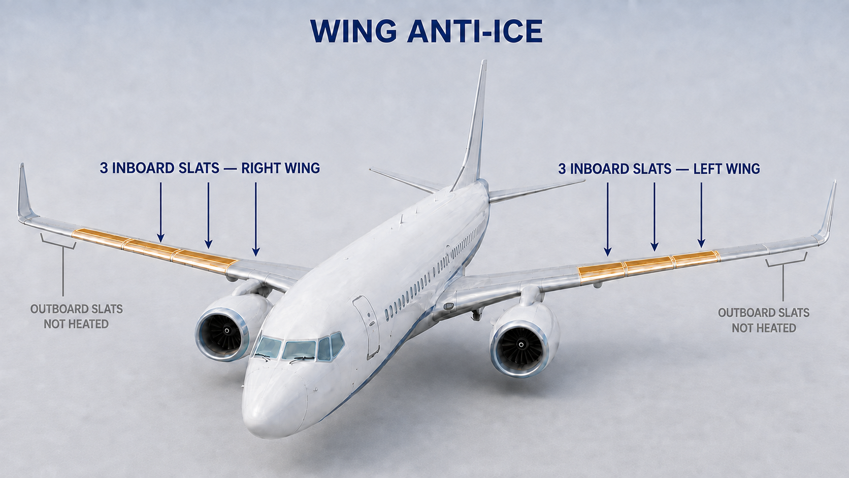
Bleed air heats the three inboard leading-edge slats on each wing; the leading-edge flaps and outboard slats remain unheated.
Description
The wing thermal anti-ice system takes engine bleed air from the common pneumatic manifold and routes it through two AC motor-operated control valves. The manifold arrangement allows either available bleed source to supply the wing system, including the required reconfiguration for engine-out operation. With a valve open, hot air passes through the three inboard leading-edge slats on that wing and is then exhausted overboard. The system remains effective with the slats in any position.
Command
In flight, selecting WING ANTI-ICE ON opens both control valves and activates icing stall-warning logic. Duct-temperature and thrust-setting logic do not control valve operation in flight.
On the ground, both valves open only while both engines remain below the takeoff-warning thrust setting and both distribution ducts remain below the thermal-switch temperature. High thrust or a hot duct closes the valves; they reopen when both conditions return to normal.
During takeoff, advancing either thrust lever above the takeoff-warning setting closes both valves, so wing anti-ice is no longer using bleed air during the takeoff roll. The WING ANTI-ICE switch itself remains ON. At lift-off, when the air/ground logic changes to AIR as the wheels leave the runway, the switch automatically trips to OFF.
Warning and indications
The valve lights show movement or a disagreement between the selected switch position and the actual position of the related wing anti-ice valve.

Dim blue: the related valve is open and agrees with the ON command.
Bright blue: the valve is moving, or its actual position disagrees with the WING ANTI-ICE switch.
Extinguished: the related valve is closed with the switch OFF.

Momentary amber: the related valve is in transit.
Steady amber: valve position disagrees with the WING ANTI-ICE switch.
Extinguished: the valve agrees with the commanded position, whether open or closed.
Engine bleed air flows through a controlled valve to prevent ice from forming on each engine cowl lip.
Description
Each engine has an electrically controlled, pressure-actuated cowl anti-ice valve. When open, it routes engine bleed air around the cowl inlet lip to prevent ice formation. The fan blades and spinner are not heated. The cowl system can operate both on the ground and in flight.
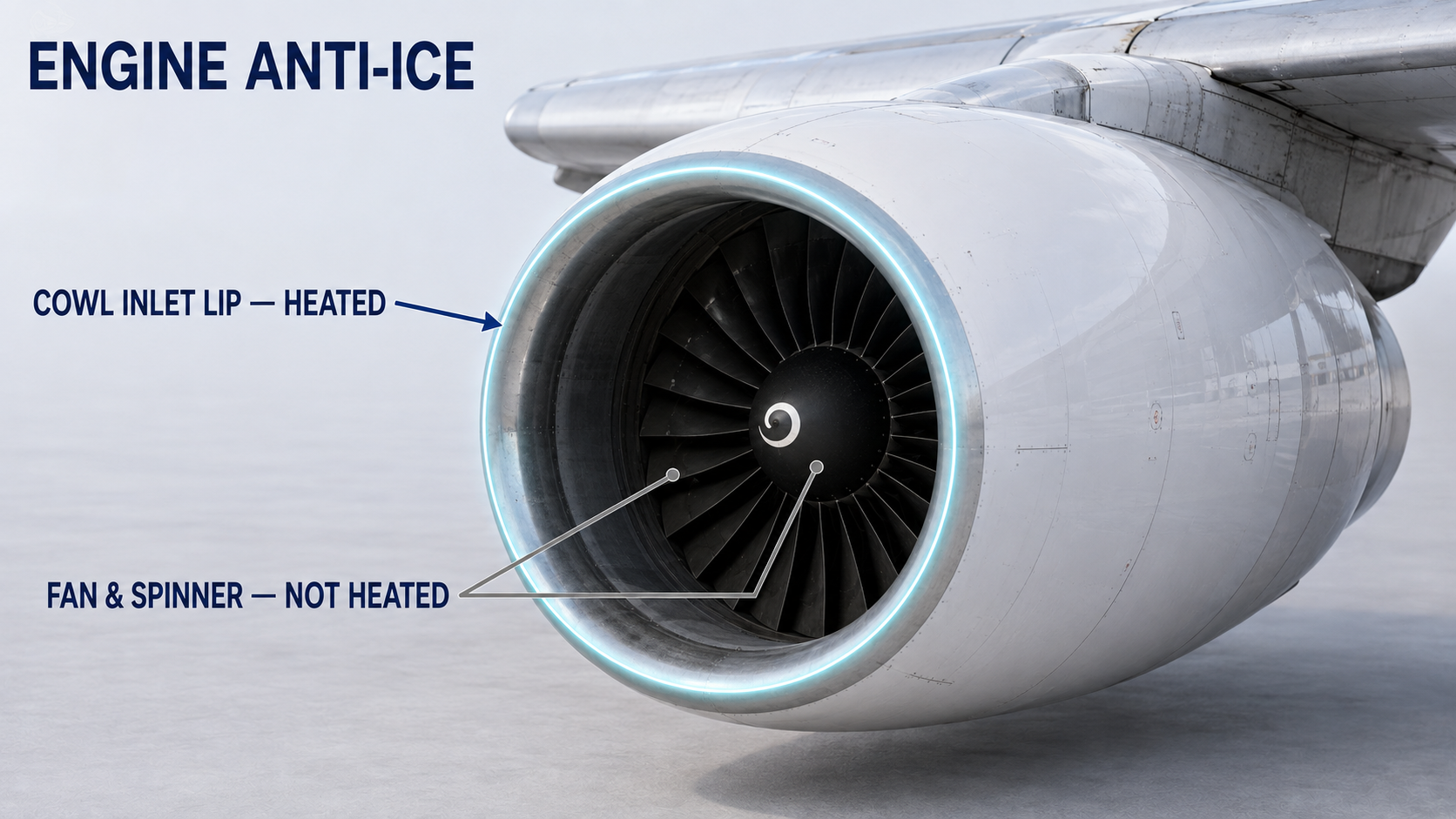
The cowl anti-ice air takeoff is upstream of the engine bleed valve. Engine anti-ice therefore remains available when the related engine bleed valve is closed; closing the bleed valve does not isolate the cowl anti-ice supply.
Command
One ENG ANTI-ICE switch controls the cowl anti-ice valve on each engine. Selecting ON opens the related valve, supplies hot bleed air to the cowl lip and activates icing stall-warning logic. Selecting OFF closes the valve; normal stall-warning logic returns only if wing anti-ice has not been used in flight.
Go deeper · MAX idle logic
With engine anti-ice ON, the supplied MAX uses icing idle with flaps UP and approach idle with the flaps extended. With engine anti-ice OFF, it uses flight idle below 15° and approach idle at 15° or more.
Warning and indications
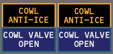
COWL ANTI-ICE · amber: excessive pressure in the duct downstream of the cowl anti-ice valve.
COWL VALVE OPEN · dim blue: the valve is open with its switch ON.
COWL VALVE OPEN · bright blue: the valve is moving or its position disagrees with the switch.
Extinguished: the valve is closed with its switch OFF.
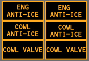
ENG ANTI-ICE · amber: cowl anti-ice is inhibited by a system failure, or an engine core anti-ice valve has failed closed.
COWL ANTI-ICE · amber: excessive pressure downstream of the cowl anti-ice valve.
COWL VALVE · momentary amber: the valve is in transit.
COWL VALVE · steady amber: valve position disagrees with the switch.
COWL VALVE extinguished: the valve agrees with the commanded open or closed position.
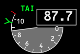
Green: the cowl anti-ice valve is open and the related ENG ANTI-ICE switch is ON.
Amber: the cowl valve position does not agree with the related switch position.
Extinguished: the cowl valve is closed and the related switch is OFF.
The crew must monitor natural ice-accretion cues because the protected surfaces do not provide a single flight-deck ice quantity display.
- Below the wiper blades: water runs upward toward the blades in flight, so ice can appear around their lower edge early.
- Wiper attachment nut: accumulation on this exposed fitting is a useful confirmation that ice may also exist elsewhere on the airframe.
- Center windshield pillar: accumulation here indicates significant icing exposure, but it does not provide a certified severity measurement.
- Wing: inspect the visible leading-edge area and cues identified by the operator.
Go deeper · Optional NG ice detection system
An optional ice detection system exists on the 737 NG, although relatively few aircraft are equipped with it. An additional detector probe is installed on the lower left fuselage below the flight deck. ICING illuminates while ice is detected. After a previous detection, NO ICE illuminates when the probe no longer detects ice and is cancelled by pressing the light. An ICE DETECTOR light on the anti-ice panel indicates a detector-system failure. Crews must identify the equipment and indication logic installed on their aircraft.
Cold-soaked fuel frost
Cold fuel remaining after a long flight can cool the wing skin enough for frost to form over the tanks, including in above-freezing ambient conditions. This non-environmental icing may appear on the lower and upper surfaces. Frost visible below the wing outboard of measuring stick No. 4 can indicate frost on the upper surface.
Anti-ice selection changes stall-warning margins so the aircraft accounts for the aerodynamic effect of icing.
- Engine anti-ice ON: icing logic is active.
- Engine anti-ice OFF: normal logic returns only if wing anti-ice has not been used in flight.
- Wing anti-ice used in flight: icing logic remains active for the rest of that flight, even after the switch is turned OFF.