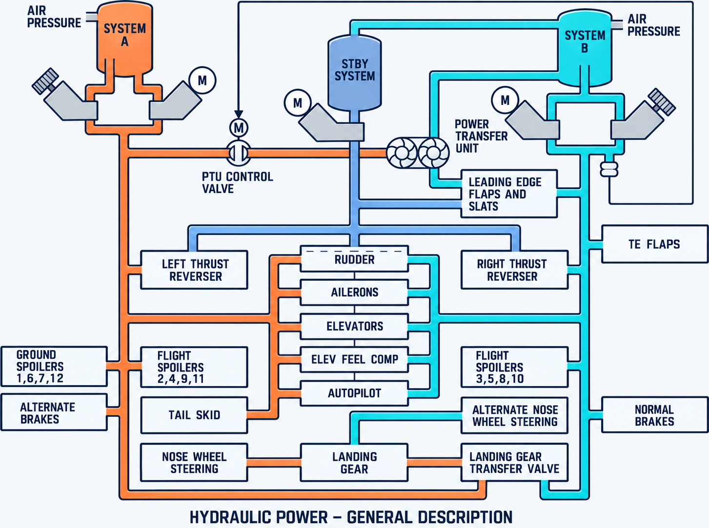
Three independent hydraulic systems provide pressure to the flight controls and aircraft services: systems A, B and standby.
Systems A, B and standby
Systems A and B are the normal hydraulic sources. Each can power all primary flight controls without reducing aircraft controllability. The standby system provides a separate backup source for selected equipment after a loss of system A or B pressure.
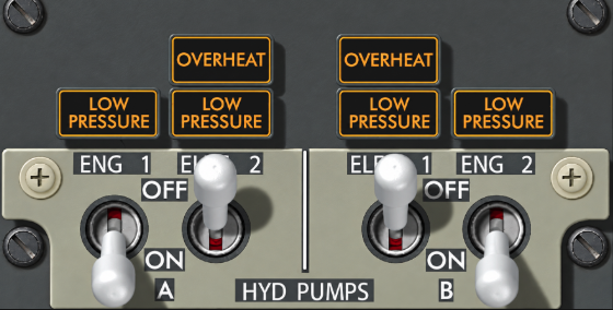
- System A: normally powered by the engine 1 driven pump and electric pump 2.
- System B: normally powered by the engine 2 driven pump and electric pump 1.
- Standby: powered by one electric motor driven pump and activated manually or automatically.
- Reservoir location: all three reservoirs are in the main wheel well.
- Reservoir pressurization: bleed air pressurizes reservoirs A and B. The standby reservoir receives pressurization and servicing through reservoir B.
Pumps and pressure
Systems A and B each have one engine driven pump and one AC electric motor driven pump. An engine driven pump supplies approximately six times the fluid volume of its related electric pump: approximately 37 US gal/min compared with 6 US gal/min. The standby electric pump supplies approximately 3 US gal/min.
| System | Engine driven pump | Electric pump |
|---|---|---|
| A | ENG 1 | ELEC 2 |
| B | ENG 2 | ELEC 1 |
| Standby | None | Dedicated standby pump |
| Minimum | Normal | Maximum |
|---|---|---|
| 2,800 psi | 3,000 psi | 3,500 psi |
- Engine pump switch ON: de-energizes the blocking valve and allows pump output into the system.
- Engine pump switch OFF: energizes the blocking valve and blocks pump output. The pump continues to rotate whenever its engine operates.
- Electric pump switch ON: supplies electrical power to the related pump.
Go deeper · Why engine pump switches remain ON at shutdown
The ON position de-energizes the engine-pump blocking-valve solenoid. Leaving the switches ON at shutdown therefore prolongs solenoid life.
Control and indication
The hydraulic panel controls the four normal pumps. The SYS display shows combined system pressure and reservoir quantity for systems A and B.
- PRESS: indicates combined output pressure from both pumps in the selected system. With both pumps OFF, it may show reservoir pressure, normally below 100 psi.
- QTY %: displays reservoir quantity from 0 to 106%.
- RF: appears below 76%. It is valid on the ground with both engines shut down, or after landing with flaps up during taxi-in.
Pump caution lights
System A combines the engine 1 driven pump with electric pump 2 and powers the landing gear, normal steering and several aircraft services.
Characteristics, quantity and reservoir design
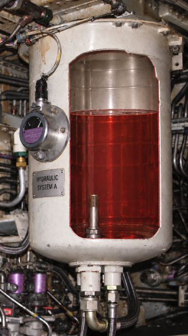
The system A reservoir is bleed-air pressurized to maintain positive flow to both pumps. Its full level is approximately 21.6 L; the refill indication corresponds to approximately 76% / 17.7 L.
- Engine-pump or engine-pump-line leak: a standpipe preserves fluid for electric pump 2. Quantity stabilizes at approximately 20%, corresponding to about 8.5 L, and electric pump pressure remains available.
- Electric-pump line or common-system leak: the reservoir drains toward zero and all system A pressure is lost.
- Normal quantity variation: quantity changes when the system is pressurized, when landing gear or leading-edge devices move, and after cold soaking.
Equipment powered
- Primary flight controls: ailerons, rudder, elevators and elevator feel.
- Spoilers: flight spoilers 2, 4, 9 and 11; ground spoilers 1, 6, 7 and 12.
- Landing gear: normal extension and retraction, plus normal nose-wheel steering.
- Brakes: alternate brakes.
- Other users: No. 1 thrust reverser, autopilot A, PTU drive and landing-gear transfer function.
Landing Gear Transfer Unit
The transfer unit allows the landing gear to retract at the normal rate when system A loses engine-driven-pump volume. System B engine-driven-pump pressure supplies the required hydraulic volume automatically when all of the following conditions are met:
- the aircraft is airborne;
- engine 1 RPM is below the specified limit;
- the landing-gear lever is UP; and
- either main landing gear is not up and locked.
System B combines the engine 2 driven pump with electric pump 1 and normally powers the flaps, leading-edge devices and wheel brakes.
Characteristics, quantity and reservoir design
The system B reservoir is bleed-air pressurized and also provides pressurization and servicing for the standby reservoir. Its full level is approximately 31.1 L; the refill indication corresponds to approximately 76% / 26 L.
- Fill and balance level: approximately 72% / 25.1 L.
- Any system B leak: indicated quantity decreases toward zero and system B pressure is lost.
- Fluid retained below indicated zero: the reservoir standpipe retains approximately 4.9 L for PTU operation.
- Standby independence: a system B leak does not prevent standby hydraulic system operation.
Equipment powered
- Primary flight controls: ailerons, rudder, elevators and elevator feel.
- Spoilers: flight spoilers 3, 5, 8 and 10.
- High-lift devices: leading-edge flaps and slats, trailing-edge flaps and autoslats.
- Brakes and steering: normal brakes and alternate nose-wheel steering.
- Other users: No. 2 thrust reverser, autopilot B, yaw damper and landing-gear transfer function.
Power Transfer Unit (PTU)
The PTU restores the hydraulic volume required to operate the autoslats and leading-edge flaps and slats at the normal rate when the system B engine-driven pump is inoperative. System A pressure drives a hydraulic motor mechanically connected to a pump which pressurizes system B fluid.
The PTU operates automatically when system B engine-driven-pump pressure is below limits and the aircraft is airborne. The additional flap condition is:
- NG YA573-YW097: flaps less than 15 but not up.
- NG YW098-YW164 and MAX: flaps not up.
A dedicated electric pump pressurizes a limited set of essential users when commanded manually or automatically.
Characteristics, quantity and reservoir design
The standby reservoir holds approximately 3.6 US gal / 13.3 L. It is connected to the system B reservoir for pressurization and servicing. The amber LOW QUANTITY light is always armed and illuminates when the standby reservoir is approximately half empty.
If the standby system leaks, standby quantity decreases to zero. System B continues to operate, but its indicated reservoir quantity decreases and stabilizes at approximately 70%.
Equipment powered
- Rudder: standby rudder power control unit.
- Leading-edge flaps and slats: extension only through the alternate-flap system.
- Thrust reversers: backup pressure for both reversers, with slower operation.
- Yaw damper: standby yaw-damper function.
Manual activation
Selecting either FLT CONTROL switch to STBY RUD starts the standby pump, isolates the associated normal-system pressure from the ailerons, elevators and rudder, and opens the standby rudder shutoff valve. Selecting ALTERNATE FLAPS ARM also starts the pump, closes the trailing-edge-flap bypass valve and arms the alternate-flap position switch.
Automatic activation
The standby pump starts automatically after a loss of system A or B pressure when the flaps are extended, the aircraft is airborne or wheel speed exceeds 60 kt, and the related FLT CONTROL switch is ON. A main rudder PCU Force Fight Monitor trip also activates the system.
- STBY RUD ON: the standby system is commanded on to pressurize the standby rudder PCU.
- STANDBY LOW PRESSURE: standby-pump output pressure is low. The light is armed only while manual or automatic standby operation is selected.
- STANDBY LOW QUANTITY: standby reservoir quantity is approximately half full; this light is always armed.
If both normal hydraulic systems lose pressure, mechanical control paths preserve limited aileron and elevator control.
The control wheels and columns remain mechanically connected to the flight controls. With no hydraulic assistance, pilot inputs operate the ailerons and elevator through manual reversion. Control forces are substantially higher and response is reduced.
- Ailerons: the control wheels mechanically position the ailerons. Control forces are higher because of friction and aerodynamic loads.
- Elevators: the control columns mechanically position the interconnected elevators. Control forces are higher because of friction and aerodynamic loads.
- Rudder: there is no manual reversion. Rudder control requires system A, system B or standby hydraulic pressure.
- Spoilers: unavailable without normal hydraulic pressure, further reducing roll response.
- Standby yaw damper: with both FLT CONTROL switches at STBY RUD, it can use control-wheel input to command the standby rudder PCU and assist the turn.
Go deeper · Reservoir foaming
If a reservoir is not correctly pressurized, fluid can foam at high altitude. Pressure may fluctuate, related LOW PRESSURE lights may blink, and MASTER CAUTION with the HYD annunciator may illuminate momentarily.