Two independently controlled turbofans provide thrust, bleed air and mechanical drive; the APU supplies auxiliary electrical and pneumatic power.
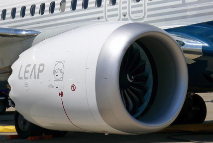
The NG uses two CFM56-7B engines and the MAX uses two LEAP-1B engines. Both are dual-rotor axial-flow turbofans. The N1 rotor comprises the fan, low-pressure compressor and low-pressure turbine. The mechanically independent N2 rotor comprises the high-pressure compressor and high-pressure turbine, drives the accessory gearboxes and is connected to the pneumatic starter.
| System | Primary function | Aircraft services |
|---|---|---|
| Engine N1 rotor | Produces most of the propulsive thrust | Fan air and low-pressure compression |
| Engine N2 rotor | High-pressure compression and combustion core | Starter connection and accessory-gearbox drive |
| Accessory gearbox | Transfers N2 mechanical power | IDG, fuel pumps, oil pump and hydraulic pump |
| APU | Independent gas-turbine power source | AC electrical power and bleed air |

Each engine has a dual-channel full-authority EEC which converts thrust-lever demand into controlled fuel flow and protects structural rotor-speed limits.
Electronic Engine Control (EEC)
Each EEC contains two independent channels. The active channel changes at every engine start or start attempt, and control transfers automatically if the operating channel fails. The EEC uses N1 as the thrust-control parameter and operates in normal, soft alternate or hard alternate mode.
- Normal mode: sensed flight conditions, thrust-lever position and bleed demand are used to calculate the N1 rating. Fuel flow is then metered to match commanded N1.
- Soft alternate mode: selected automatically when normal-mode inputs are lost. The last valid flight conditions are retained so the transfer produces no immediate thrust change. The ON and ALTN indications can both be visible.
- Hard alternate mode: entered when a thrust lever is retarded to idle in soft alternate, or when ALTN is selected manually. The alternate schedule gives rated thrust or more for a given lever position; maximum rated thrust may be reached before the forward stop.
- Structural protection: N1 and N2 redline overspeed protection remains available in normal and alternate modes. EGT redline protection is not provided during normal engine operation and the crew must observe the EGT limit.
Go deeper · Idle schedules
The EEC selects the idle required by aircraft configuration. Ground minimum idle is used on the ground. Flight minimum idle is used during most flight conditions. A higher approach idle improves acceleration for a go-around. On the NG it is selected with either engine anti-ice on, or below 19,000 ft with a main gear down or flap 15 or greater. The MAX separately schedules icing idle with flaps up, gear not down and locked, and engine anti-ice on; approach idle applies with flap 15 or greater, or with flaps not up and engine anti-ice on.
Start function and protection
A ground start requires electrical power and pneumatic pressure from the APU, an external air source or the other operating engine. Selecting GRD closes the related engine bleed valve and opens the start valve. Bleed air drives the starter and rotates N2 through the accessory gearbox.
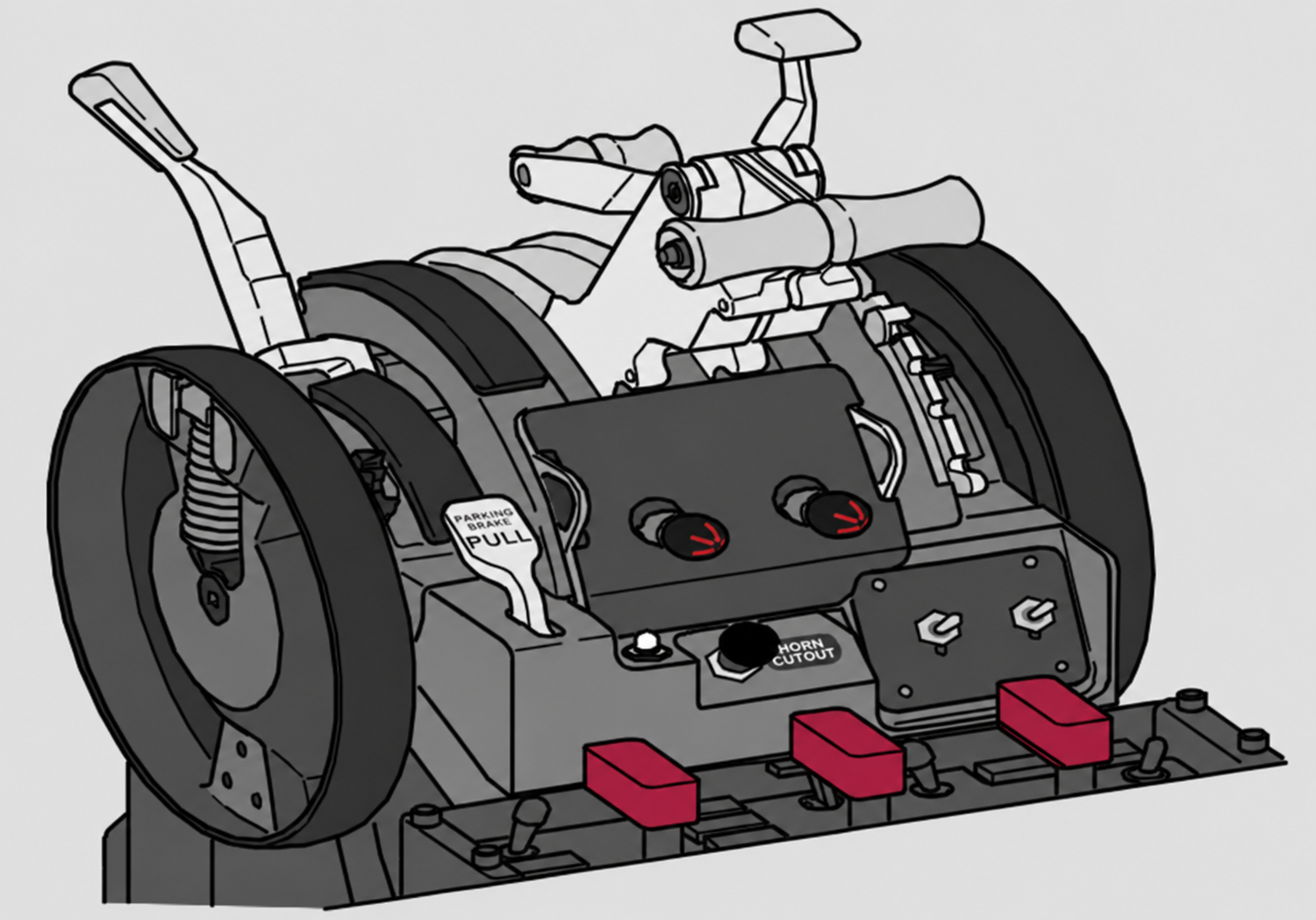
- Motoring: wait for the recommended 25% N2 or maximum motoring before moving the engine start lever.
- Start lever IDLE: the spar and engine fuel valves open and the EEC supplies fuel and ignition. EGT must rise and N2 must continue to accelerate.
- Starter cutout: at approximately 56% N2 on the NG and 63% N2 on the MAX, the start switch releases to OFF, the start valve closes and the engine bleed valve returns to its selected position.
During a ground start, the EEC monitors for an impending hot start, compressor stall, EGT start-limit exceedance and wet start. For an impending hot start or stall, the white EGT box flashes and applicable EEC software removes ignition and fuel. An EGT start-limit exceedance turns the indication red and causes automatic fuel and ignition cutoff. If EGT does not rise within 15 seconds after selecting IDLE, wet-start logic shuts off fuel and ignition.
Indications and warnings
N1 and EGT are the primary engine indications. Secondary indications are N2, fuel flow, oil pressure, oil temperature, oil quantity and vibration. Secondary data appears automatically at initial display power-up, in flight when a start lever is moved to CUTOFF, when N2 falls below idle, or when a secondary parameter exceeds its normal range.

Steady indicates that the start valve is open and starter air is supplied. Blinking indicates an uncommanded valve opening.

Oil pressure is at or below the red line. A new condition blinks for 10 seconds before remaining steady.

An oil-filter bypass is impending. On the NG it monitors the scavenge filter; on the MAX it monitors the oil supply filter.
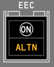
The EEC has transferred automatically to alternate control or ALTN has been selected manually. ON and ALTN can both be visible in soft alternate mode.
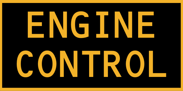
An engine-control fault makes the system not dispatchable. The light is displayed with the engine running on the ground below 80 kt before takeoff, or approximately 30 seconds after touchdown.
Fuel, ignition and oil are scheduled around the EEC, while the thrust reverser redirects fan flow for ground deceleration.
Ignition
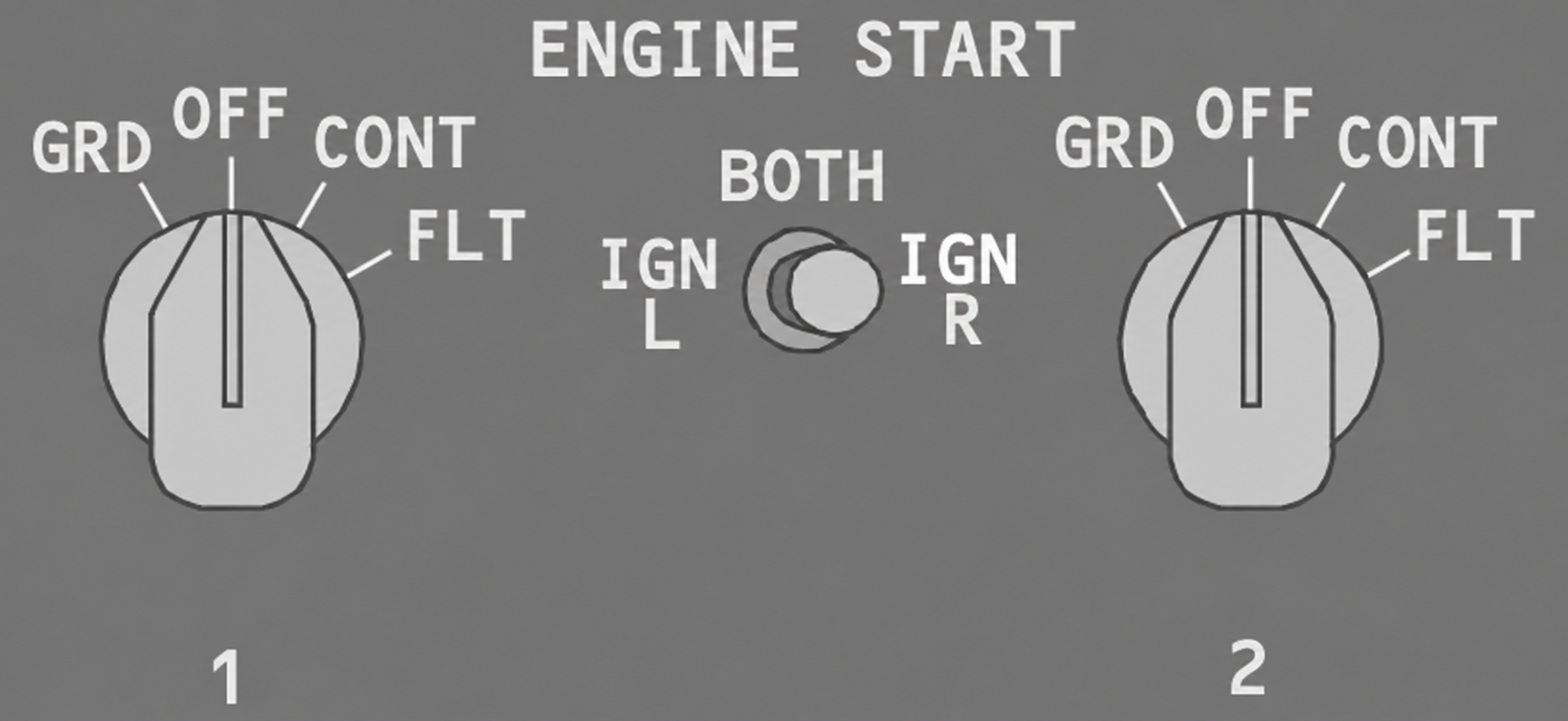
Each engine has two independent igniter plugs. The left igniter is powered by the associated AC transfer bus; the right igniter is powered by the AC standby bus. The ignition-select switch chooses L, BOTH or R for both engines.
- GRD: opens the start valve and arms the selected igniter for a ground start. During an inflight start, both igniters are armed.
- OFF: normal position with ignition off, although automatic relight logic can energize both igniters after a rapid uncommanded N2 decrease or when N2 falls below the applicable idle schedule.
- CONT: continuously energizes the selected igniter while the engine operates and the start lever is at IDLE; both are used if inflight N2 falls below idle.
- FLT: energizes both igniters whenever the start lever is at IDLE.
Oil system
Each engine has an independent, self-contained oil system. An engine-driven pressure pump supplies oil to the bearings and accessory gearbox. Engine-driven scavenge pumps recover the oil from the sumps and gearbox and return it to the tank after cooling and separation.
- Oil pressure: white in the normal range, amber in the caution range and red at the operating limit. LOW OIL PRESSURE appears at or below the red line.
- Oil temperature: white normally, amber in the caution range and red at the operating limit.
- Oil quantity: shows usable tank quantity. A temporary decrease during start, takeoff or climb does not by itself affect engine operation.
- Filter protection: the oil automatically bypasses a saturated filter; OIL FILTER BYPASS appears before bypass occurs.
Engine fuel system
Tank pumps deliver fuel through the spar shutoff valve to the engine-driven fuel pumps, heat exchangers and filter. The EEC meters fuel in the HMU on the NG and the FMU on the MAX. Both the spar and engine fuel valves must be open for engine operation; either the start lever at CUTOFF or a pulled fire switch closes both valves.
Go deeper · Fuel is also the oil heat sink
The fuel/oil heat exchanger transfers engine-oil heat into the fuel. This cools the oil and warms the fuel before it reaches the metering unit and combustor.
Thrust reverser
Each hydraulically operated reverser moves translating sleeves aft and deploys blocker doors so fan discharge is redirected forward through cascade vanes. Engine 1 normally uses hydraulic system A and engine 2 system B; the standby system provides slower alternate operation if the normal source is lost.
- Interlock: reverse cannot be selected until the forward thrust lever is at IDLE, and the reverse lever is held near reverse idle until deployment is sufficient.
- REV amber: the reverser has moved from stowed. REV green: deployment is complete.
- NG REVERSER: a valve, sleeve-position, auto-restow or synchronization-lock fault exists.
- MAX REVERSER LIMITED: a ground fault exists, or an inflight fault will prevent deployment or limit reverse to idle.
The tail-mounted APU is an automatically controlled gas turbine which supplies auxiliary AC electrical power and pneumatic air.
APU control
- OFF: normal shutdown position. If the APU is running, the generator is removed from the buses and the bleed valve closes; the APU continues through an automatic 60-second cooling period.
- ON: normal running position.
- START: momentary selection. Releasing the switch to ON initiates the fully automatic start sequence.
APU operation requires the flight-deck APU fire switch and external ground-control fire handle to be in, with the BATTERY switch ON. Start power normally comes from transfer bus 1; the main battery supplies the starter-generator when AC power is unavailable. Selecting the battery OFF removes ECU power and shuts down the APU.
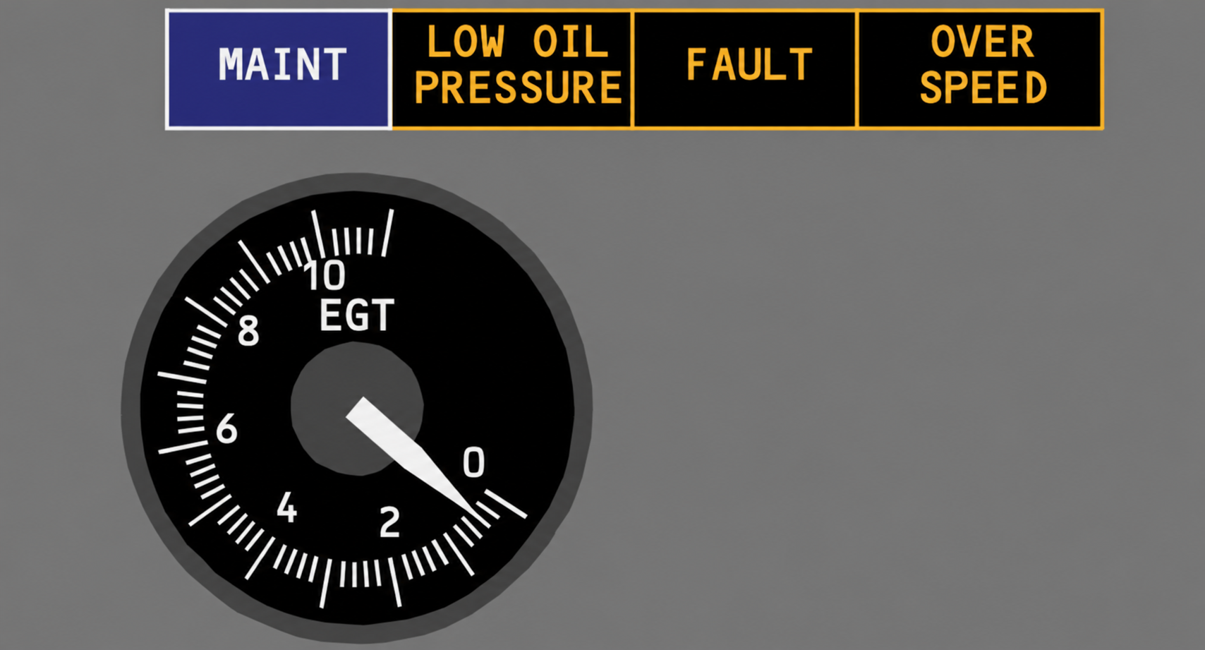
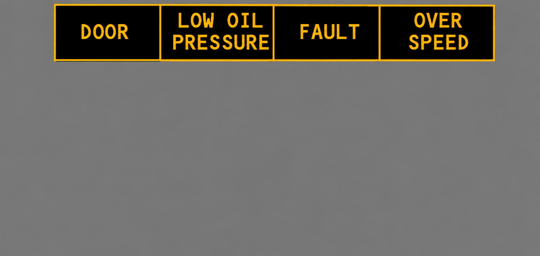
APU system
The APU can start and operate up to the aircraft maximum certified altitude. It can power both transfer buses on the ground or in flight. Pneumatically, it supplies both packs on the ground or one pack in flight and provides air for engine starting.
- Fuel: supplied from the left fuel manifold when AC pumps operate; without AC pump pressure, the APU suction-feeds from tank 1. Fuel is heated automatically during operation.
- Air inlet: opens automatically before the start sequence. Ignition and fuel are introduced only after the door reaches the required position and the APU reaches the required speed.
- Ready for load: the blue APU GEN OFF BUS light illuminates when the APU can accept electrical or bleed load.
- Start time: the automatic cycle can take up to 120 seconds and terminates if speed and acceleration targets are not achieved.
- Bleed stabilization: allow two full minutes after start before using APU bleed air.
- Shutdown: selecting OFF provides the required one-minute unloaded cooling period automatically before fuel and the inlet door close.
Go deeper · ECU load management
The ECU schedules fuel, speed and protective shutdown. With excessive EGT or speed under electrical load, it sheds load. During an engine start it sheds electrical load before reducing bleed extraction. Outside engine start, it reduces bleed extraction through the inlet guide vanes while maintaining electrical load. In flight with the APU as the sole electrical source, galley and main buses are shed automatically; additional IFE shedding occurs if required.
Indications and warnings
- LOW OIL PRESSURE: normal during the start until pressure rises; after the start cycle, low pressure causes automatic shutdown.
- FAULT: an APU malfunction has initiated automatic shutdown. It also identifies a failed start or a fuel valve that fails to close after shutdown.
- OVERSPEED: the RPM limit was exceeded and caused automatic shutdown, or overspeed shutdown protection failed its self-test during normal shutdown.
- APU GEN OFF BUS: blue when the generator is available but not connected to a bus; during start it also confirms that the APU is ready to accept load.