The 737 stores its usable fuel inside three structural tanks that supply both engines and the APU.
Where is the fuel?
737-800 NG · TOP VIEW- Main tanks 1 & 2: integral to the left and right wings.
- Center tank: wing center section, extending into the wing roots.
| Tank | 737-800 NG | 737-8200 MAX |
|---|---|---|
| Main 1 / Main 2 (each) | 3,915 kg · 4,876 L | 3,869 kg · 4,819 L |
| Center | 13,066 kg · 16,273 L | 12,990 kg · 16,179 L |
| Total | 20,896 kg · 26,025 L | 20,728 kg · 25,817 L |
The fuel pumps draw fuel from the tanks and deliver it under pressure to the engine feed manifolds, providing a continuous supply to the engines during normal operation.
Fuel pump
- Two pumps per tank: six AC-powered pumps in total.
- Cooling & lubrication: provided by fuel passing through the pump.
- Center pumps: higher output pressure than main tank pumps.
Two AC-powered pumps are assigned to each tank, giving six pumps in total. Fuel passing through each pump provides cooling and lubrication. The center tank pumps deliver higher pressure than the main tank pumps.
Fuel supply
When all six pumps operate, the center tank pumps produce more pressure than the main tank pumps, so center tank fuel is consumed first. To stop using the center tank, the crew switches its pumps OFF and the main tank pumps supply the engines. There is no fuel tank selector: pump selection and pressure establish the source.
If all pumps are lost, each engine-driven fuel pump can draw from its corresponding main tank through the suction-feed path. This path may become restricted at altitude, with a risk of thrust deterioration or engine flameout.
Follow the fuel
SIMPLIFIED FEED SCHEMATICCenter pumps supply both engine feed lines at higher pressure. Main tank pumps remain on, but center fuel takes priority. The crossfeed valve is closed.
Pump control and warning
Six switches on the overhead fuel panel control the two AC pumps in each tank.
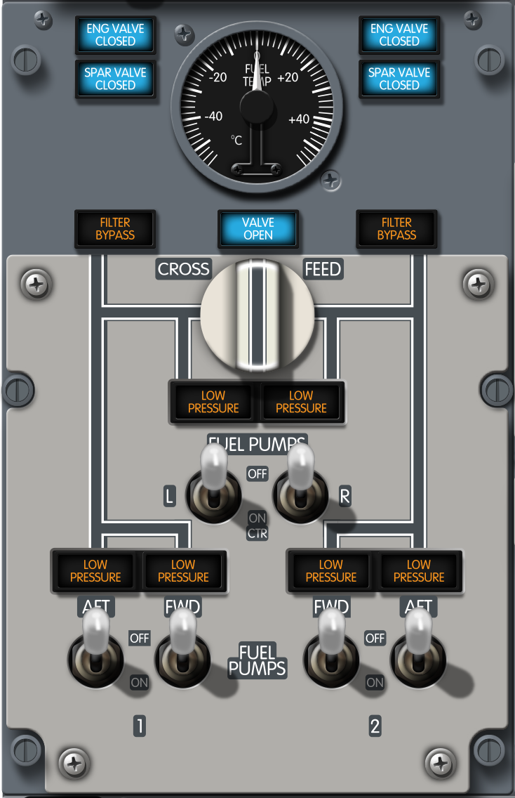

Illuminated (amber) – fuel pump output pressure is low, or FUEL PUMP switch is OFF.
On center tank pumps, the light is extinguished when the associated switch is OFF.
Center Pump Automatic
Each center tank pump automatically stops after its own pressure sensor detects low pressure for a short delay, although the switch remains ON. Selecting that switch OFF resets the automatic shutdown logic; selecting it ON again reactivates the pump until it is switched off or the logic stops it again. This delay is a separate function from the 10-second MASTER CAUTION logic. Intentional dry running of a center tank pump with its low-pressure light illuminated is prohibited.
Go deeper · A dry pump can lose its prime
Technical background material notes that a center pump left running dry for roughly ten minutes can lose the fuel needed to prime itself and may remain inoperative after refuelling. A LOW PRESSURE light that remains illuminated for more than about 19 seconds after selection can be a maintenance clue. These are indicative troubleshooting values, not a crew reset procedure: switch the affected pump OFF and apply the aircraft’s current approved operational and maintenance procedure.
Scavenge pump
The scavenge jet pump transfers residual fuel from the center tank to main tank No. 1, the left wing tank. Transfer begins when main tank No. 1 is approximately half full.
- Transfer: residual center fuel → main tank 1.
- Required switch: No. 1 FWD fuel pump ON.
- Starts: main tank 1 approximately half full.
- Continues: for the remainder of the flight once started.
- Indicative transfer rate: at least approximately 100 kg/h and commonly nearer 200 kg/h; confirm effectivity.
APU fuel
With an AC fuel pump operating, the APU receives pressurized fuel from the left manifold. Without AC pump pressure, it can draw fuel by suction from main tank 1. The tank feeding the left manifold therefore determines the pressure-fed source available to the APU.
- AC pumps operating: APU fed from the left fuel manifold.
- AC pumps not operating: APU suction feed from main tank 1.
Three valve types control fuel isolation and the connection between the left and right engine feed manifolds.
Engine valve
The engine fuel shutoff valve is fuel-actuated and solenoid-controlled from the battery bus. It isolates fuel at the engine and closes when the associated engine start lever is moved to CUTOFF or the engine fire switch is pulled.
- ENG VALVE CLOSED extinguished: valve open.
- Dim blue: valve closed.
- Bright blue: valve in transit or disagreement between commanded and actual position.

Spar valve
The spar fuel shutoff valve is installed at the engine-mounting wing station. A DC motor powered by the hot battery bus operates it. Like the engine valve, it closes with the associated start lever at CUTOFF or when the engine fire switch is pulled.
Go deeper · Spar valve electrical supply
The spar valve motor is powered by the hot battery bus. The configuration information supplied for this course also describes a small autonomous backup battery, recharged by DC bus 2, which preserves engine-shutdown capability after a total electrical power loss. Confirm this installation on the applicable aircraft documentation.
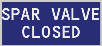
- SPAR VALVE CLOSED extinguished: valve open.
- Dim blue: valve closed.
- Bright blue: valve in transit or disagreement between commanded and actual position.
Crossfeed valve
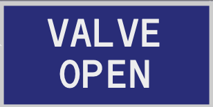
The crossfeed valve connects the left and right engine fuel manifolds. Its DC motor is powered by the battery bus. Opening it allows one pressurized manifold to supply both engines; it does not transfer fuel into the opposite tank. Continued asymmetric feeding changes lateral fuel balance by changing which tank is consumed.
- VALVE OPEN extinguished: crossfeed valve closed.
- Dim blue: crossfeed valve open.
- Bright blue: valve in transit or disagreement between commanded and actual position.
Fuel quantity indications and alerts help the crew monitor usable fuel, tank balance and the fuel predicted at destination.
Fuel display
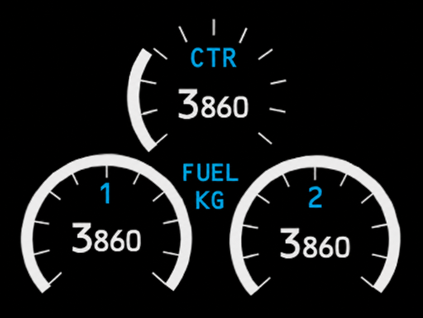
Two fuel-quantity display layouts can be found across the 737 NG fleet. Round gauges are generally associated with earlier NG aircraft, while later NG aircraft and the 737 MAX use a digital presentation with a totalizer. Display fit depends on aircraft effectivity, so the installed layout should be confirmed in the configuration installed on the aircraft.
Go deeper · How fuel quantity is measured
Tank units act as electrical capacitors, with fuel forming the dielectric between their electrodes. Because capacitance changes with the amount and properties of the fuel, the FQIS combines the tank-unit signals and calibration data to calculate usable quantity. Where installed, a densitometer compensates for fuel density so the displayed mass is more accurate as fuel properties change.
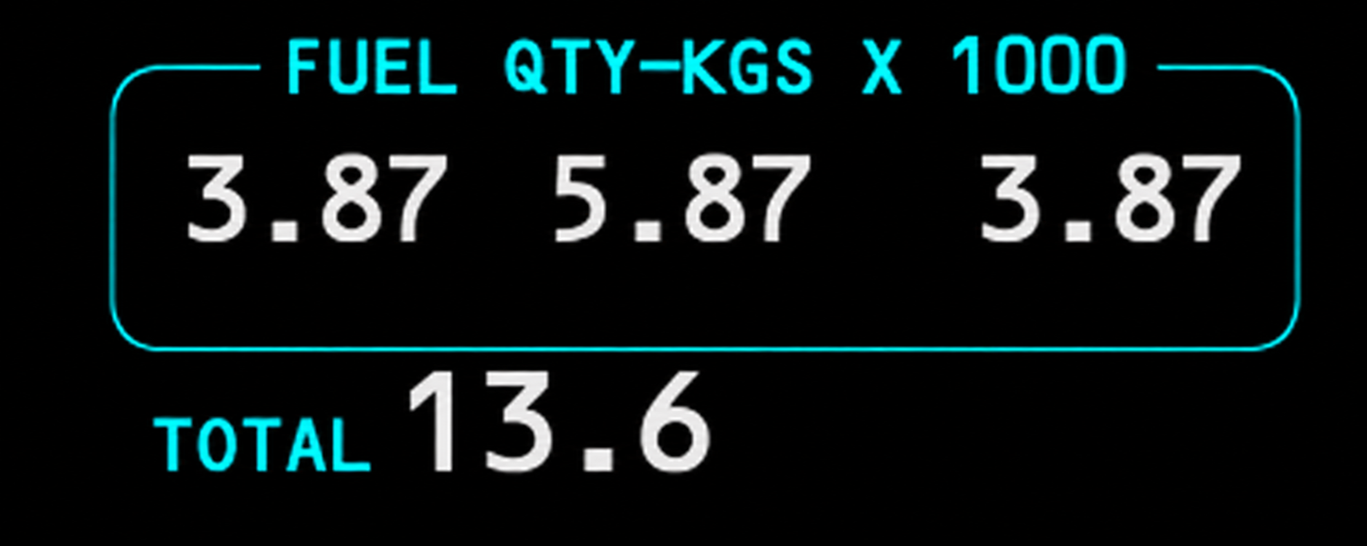
Fuel QTY alert
- Quantity indication: usable fuel; available with AC or DC power.
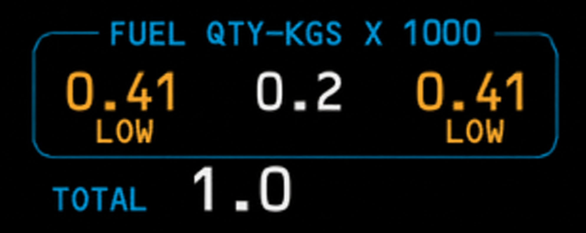
Appears below 453 kg in either main tank and clears when that tank reaches 567 kg.
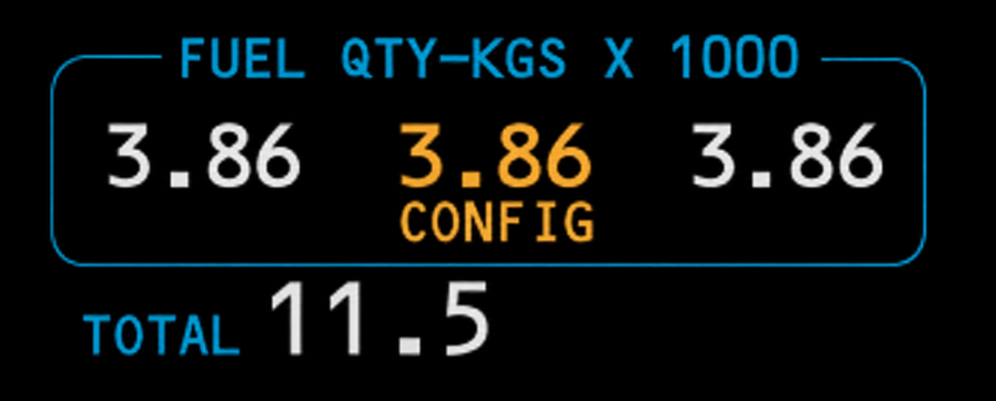
Appears with either engine running when center tank quantity is above 726 kg and both center pump switches are OFF. It clears when both engines are stopped, center quantity falls below 363 kg, or either center pump switch is ON.
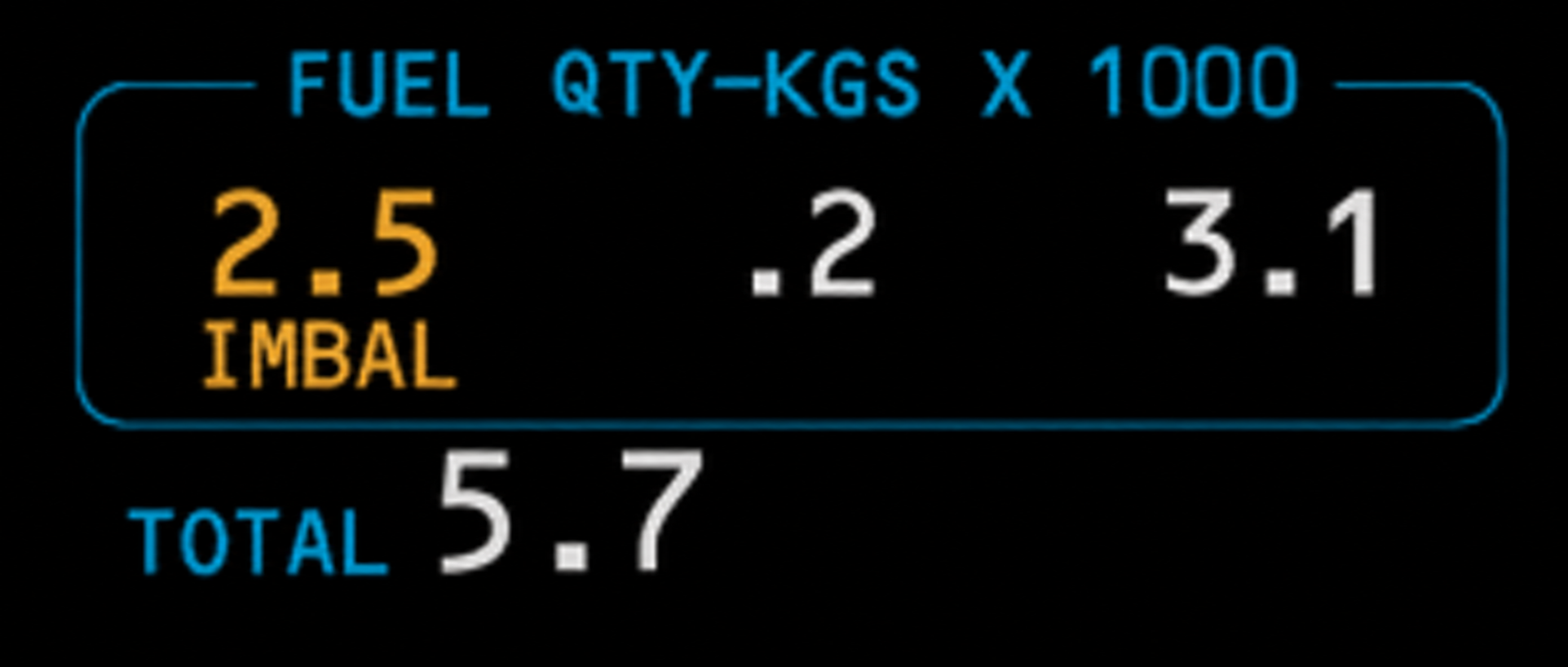
Appears on the lower-quantity main tank when the difference exceeds 453 kg. It clears when the difference decreases to 91 kg.
LOW takes precedence over IMBAL when both conditions exist.
Go deeper · Quantity indication is not perfectly exact
Indicated tank quantity may differ from actual quantity by up to 2.0% on the ground and 2.5% in flight on the NG, and by up to 2.5% in flight on the MAX. These are indication-accuracy statements, not extra usable fuel or operational allowances.
NG cockpit presentations vary by aircraft effectivity and include both round indicators and a numeric layout with a total quantity display. A different display layout alone does not identify a MAX.
Filter alert

Illuminated (amber) – impending fuel filter bypass due to a contaminated filter.
Configuration data supplied for this course: the alert is triggered at approximately 11.5 PSI differentialand the bypass opens at approximately 15 PSI. Confirm aircraft applicability.
MAX alert
In addition to the fuel alerts already available on the 737 NG, the 737 MAX provides extra messages related to fuel quantity and the FMC fuel prediction.
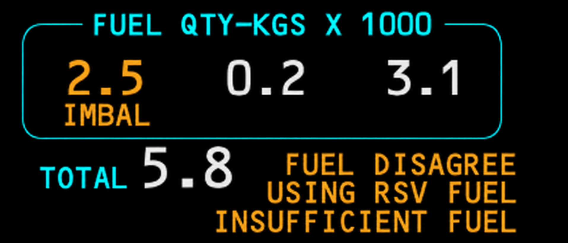
The supplied MAX display can present the three fuel prediction and quantity-consistency alerts described below.
- FUEL DISAGREE: totalizer quantity and FMC calculated quantity disagree.
- USING RSV FUEL: predicted destination fuel is below the entered RESERVES value.
- INSUFFICIENT FUEL: predicted destination fuel is below 900 kg.
Fuel temperature is measured in main tank 1 and must remain inside the applicable warm and cold operating limits.
- Sensor: main tank 1.
- Display: overhead FUEL TEMP indicator.
- Power: AC.
Main tank No. 1 is used because it is normally the coldest tank; it receives less warming from the smaller hydraulic system A. If temperature approaches the applicable minimum, descending into warmer air or increasing speed can increase fuel temperature through warmer ambient air or kinetic heating. Any response must follow the current operating procedure and flight constraints.
- Limit: maximum +49°C; minimum before takeoff and in flight −43°C or freezing point +3°C, whichever is higher.
Worked example · Choose the warmer limit
If the fuel freezing point is −47°C, adding 3°C gives −44°C. The warmer of −44°C and −43°C is −43°C, so −43°C is the applicable minimum. If the freezing point were −40°C, the minimum would instead be −37°C.
The rule is not simply “freezing point plus three” in every case. Fuel-system icing-inhibitor additives do not change the minimum.
Go deeper · Cold-soaked fuel frost
After a long flight with cold fuel, frost can form on the upper or lower wing skin over the tanks even when outside air temperature is above freezing. This is cold-soaked fuel frost, not atmospheric in-flight icing. Dispatch relief applies only within an approved, marked CSFF area and under the precise inspection and thickness criteria in the applicable procedure.
Refuelling
- Single-point station: right wing.
- Tank full: automatic shutoff closes the corresponding fueling valve.
- Manual defueling valve: connects engine feed system and fueling station.
- Ground functions: refueling, defueling and tank-to-tank transfer.
Go deeper · A separate way to measure fuel
There are six measuring sticks in each main tank and four in the center tank: sixteen in total. A stick is withdrawn and magnetically latched to an internal float. Its reading provides a physical measurement that can be compared with the indicated quantity using the applicable conversion information.
Nitrogen Generation System
The NGS converts engine bleed air into nitrogen-enriched air and sends it to the center fuel tank. Reducing the oxygen content in the tank ullage lowers its flammability while ignition-source protection remains the primary safeguard.
Operation is automatic and transparent to the flight crew. The system starts after takeoff, operates through climb, cruise, descent and landing, then continues briefly during taxi. It needs no crew action and has no flight deck indication; its operability lights are in the right main wheel well near the APU fire control panel.
- Input: bleed air.
- Output: nitrogen-enriched air to the center tank, reducing flammability.
- Operation: automatic; no flight-deck control or indication.
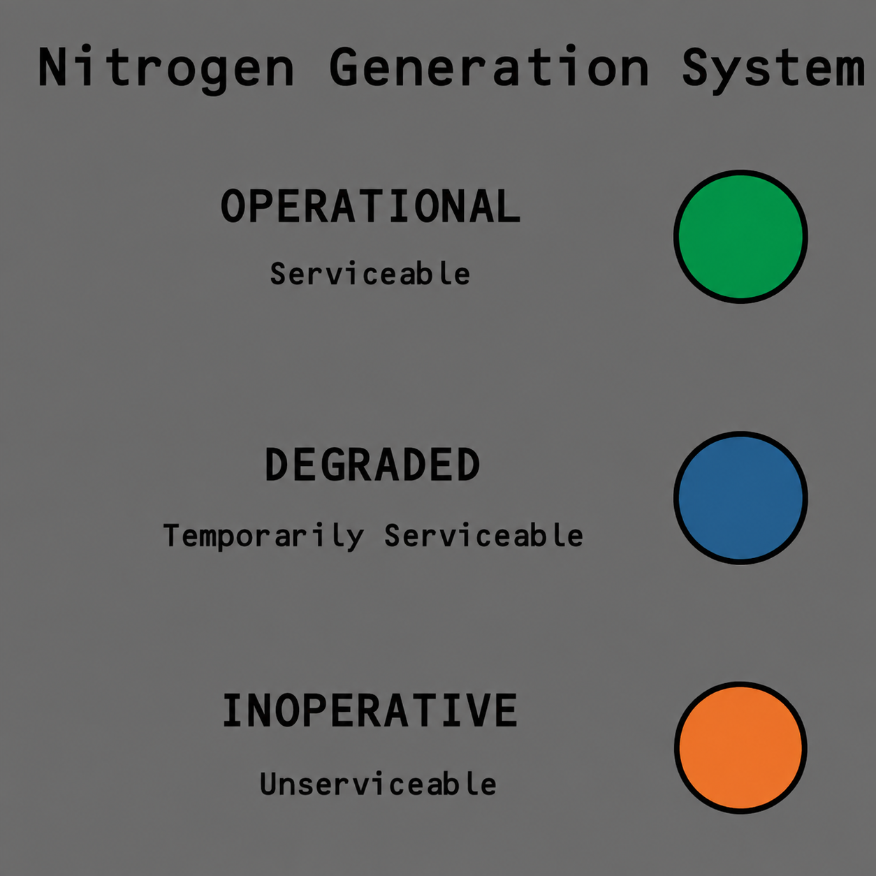
The NGS serviceability panel is in the right main wheel well, near the APU fire-control panel. A green light indicates OPERATIONAL, a blue light indicates DEGRADED and an amber light, or no illuminated light, indicates INOPERATIVE.
Go deeper · Availability and automatic shutdown
NGS is effectivity-dependent on the NG and is also fitted to the MAX. It is not a MAX-only feature. The system can automatically shut down for conditions including an engine not running in flight, cargo/main-deck fire or smoke detection, left pack overheat or an open center refueling valve. Dispatch decisions belong to the applicable MEL.
Go deeper · Why nitrogen reduces flammability
The air-separation module sends nitrogen-enriched air to the empty space above the center-tank fuel and vents the oxygen-enriched stream overboard. FAA technical background uses approximately 12% oxygen as a representative concentration at which ignition is not sustained. This figure explains the design objective; it is not a flight deck target or crew-controlled parameter.
Use these questions to check whether the key system relationships are clear.
Three free questions with explanations. No account required.
FREE PRACTICE · QUESTION 1 OF 3