Bleed air links the pneumatic sources to engine starting, air conditioning, pressurization, anti-ice and several supporting systems.
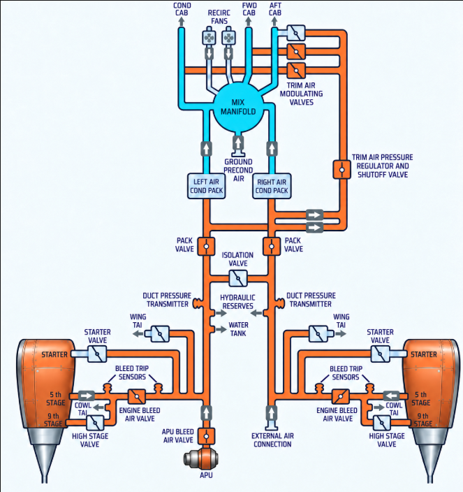
Engines normally supply the pneumatic system in flight; the APU and an external source provide alternative supply on the ground.
Sources
- Engines: the normal inflight source. Low-stage compressor air is sufficient during takeoff, climb and most cruise conditions. The high-stage valve modulates toward open whenever low-stage bleed air is insufficient.
- APU: supplies both packs on the ground or one pack in flight and provides pneumatic air for engine start.
- External air: connects to the right side of the manifold and can supply air conditioning or engine starting.
The engine bleed valve acts as both a pressure regulator and a shutoff valve. A precooler uses engine fan air to reduce bleed-air temperature before distribution.
Go deeper · External engine start
Engine No. 1 is normally started first so ground personnel can disconnect the ground-air unit and clear the area after that start. Engine No. 2 is then started using crossbleed air from engine No. 1.
Command
Engine and APU bleed switches
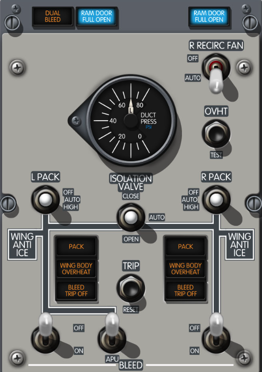
- ENG BLEED OFF: commands the related engine bleed valve closed.
- ENG BLEED ON: allows the related valve to regulate and supply the manifold when pressure and protection logic permit.
- APU BLEED OFF: commands the APU bleed valve closed.
- APU BLEED ON: allows APU bleed air into the manifold. The valve also closes automatically when the APU shuts down.
Pack switches
- OFF: closes the related pack valve.
- AUTO — both packs operating: each pack regulates to low flow.
- AUTO — one pack operating in flight: with the flaps up, the operating pack regulates to high flow.
- AUTO — one pack supplied by the APU: with both engine BLEED switches OFF, the operating pack regulates to high flow.
- HIGH: commands high pack flow for increased ventilation.
Automatic high flow for a single engine-supplied pack is inhibited on the ground or with the flaps extended to preserve engine performance.
Isolation valve switch
- CLOSE: commands the isolation valve closed and separates the left and right manifolds.
- AUTO — closed: the valve closes when both engine BLEED switches are ON and both PACK switches are in AUTO or HIGH.
- AUTO — open: the valve opens automatically when either engine BLEED switch or either PACK switch is OFF.
- OPEN: commands the isolation valve open, joining both manifold sides.
Indications and warnings

NG — BLEED TRIP OFF: indicates excessive bleed-air temperature or pressure. The related engine bleed air valve closes automatically and a reset is required.
MAX — BLEED: indicates excessive temperature, overpressure or a bleed-air-system fault. Illumination of both BLEED lights can also identify an incorrect configuration after takeoff or a go-around.
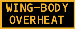
Indicates a bleed-duct leak in the related engine strut, inboard wing leading edge or air-conditioning bay. The left indication also monitors the keel beam and APU bleed duct.

Indicates a configuration that can allow engine bleed pressure to backpressure the APU. Engine thrust must remain at idle while the light is illuminated.
Two packs cool and condition bleed air before it is mixed with filtered recirculated air and distributed to the flight deck and cabin.
Temperature control
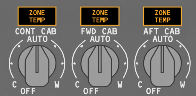
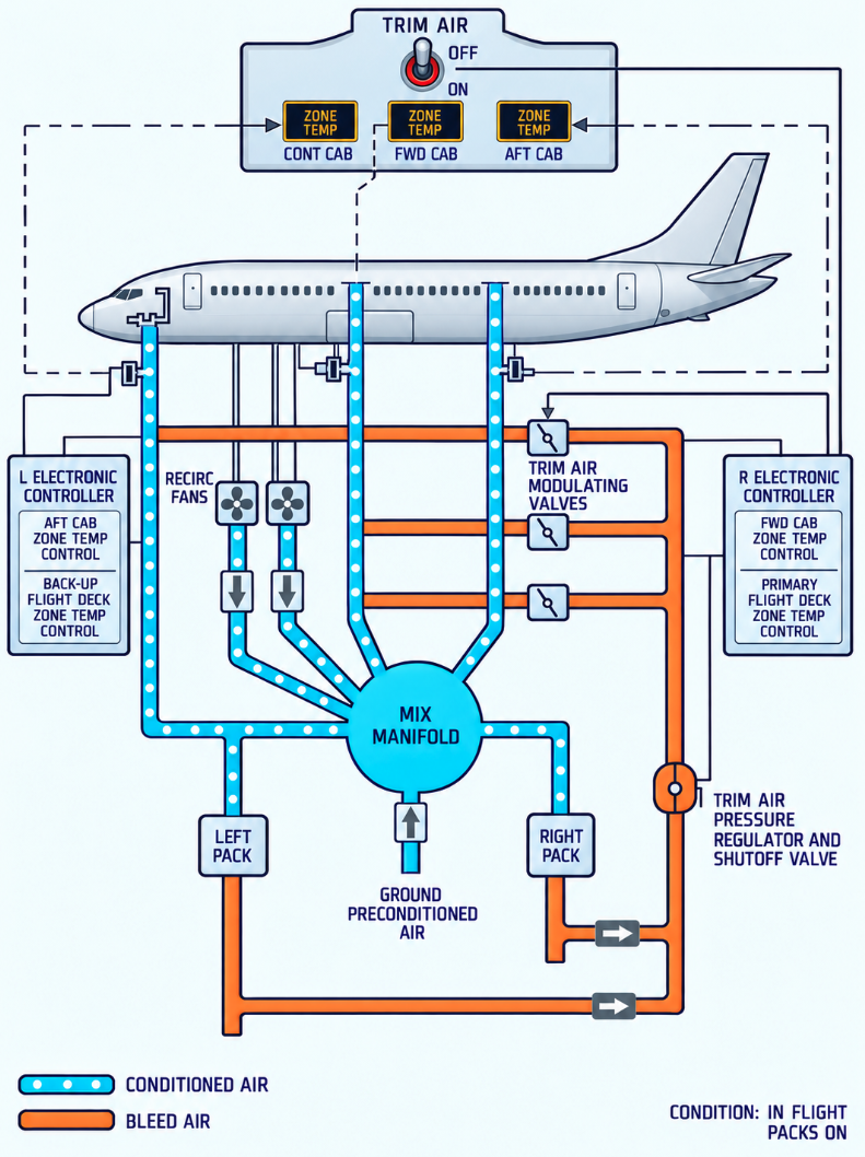
On the applicable NG three-zone system and on the MAX, three selectors set the desired temperature for the flight deck, forward cabin and aft cabin. The packs produce air cold enough for the zone demanding the most cooling; individual trim-air valves then add hot bleed air to the zone ducts as required.
- Two packs or one pack with TRIM AIR ON: all three zones retain individual temperature control.
- One pack with TRIM AIR OFF: the operating pack targets the average demand of all three zones.
- All selectors OFF: the MAX controllers command fixed pack temperatures of approximately 24°C left and 18°C right.
- Duct overheat: the affected trim-air valve closes and the related zone-temperature light illuminates.
Go deeper · Controller redundancy
Each pack has primary and standby control, with standby control located in the opposite-side controller. If both controls for one pack fail, that pack can continue uncontrolled until an overtemperature protection trips it. Zone-control failures cause the remaining demands to be averaged as required.
Equipment cooling system
Supply fans deliver cool air to flight-deck displays and equipment in the electrical/electronic bay. Exhaust fans collect heated air from those units and from flight-deck electronic and circuit-breaker panels. Each duct has a normal and an alternate fan.
- SUPPLY / EXHAUST NORM: the normal fan operates.
- ALTN: the alternate fan operates and should restore airflow within approximately five seconds.
- Smoke detection: supply- and exhaust-duct detectors monitor the system and generate EQUIP SMOKE on the MAX when smoke is sensed.
Recirculation fans
The applicable NG three-zone system uses two AC-powered recirculation fans. The MAX also uses two recirculation fans within its IASC-controlled three-zone configuration. They draw air from the passenger cabin and equipment bay, filter it and return it to the mix manifold, reducing pack load and engine bleed demand while maintaining cabin airflow.
- AUTO in flight: the left fan stops if either pack is HIGH; the right fan stops only if both packs are HIGH.
- AUTO on ground: the left fan stops if both packs are HIGH; the right fan continues to operate.
- OFF: the related fan is commanded off.
Indications and warnings

NG YF501–YW164 and MAX: indicates a pack trip off or simultaneous loss of the primary and standby pack controls.

NG YF501–YW164 and MAX: indicates an overheat in the related zone duct or a temperature-control failure. The associated trim-air valve closes for duct overheat.
Indicates inadequate airflow in the related supply or exhaust cooling duct. Selecting the associated fan to ALTN should start the alternate fan and extinguish the light after airflow is restored.

Illuminates with MASTER CAUTION and OVERHEAD when smoke is detected in an equipment-cooling duct.
The aircraft controls cabin pressure by regulating how much conditioned air leaves through the outflow valves.
Valves and pressure control
The main outflow valve near the aft fuselage meters most cabin-air discharge. Two positive pressure-relief valves limit differential pressure to 9.1 psi, while a negative-relief valve prevents ambient pressure from exceeding cabin pressure.
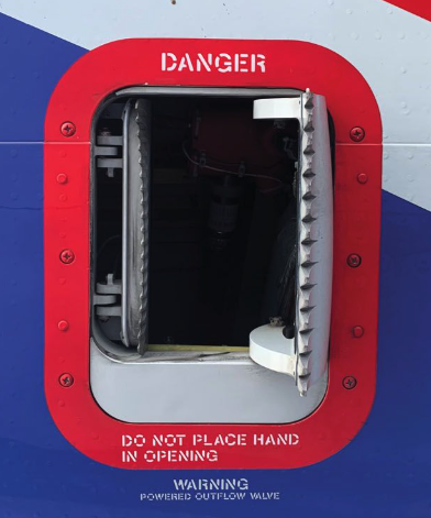
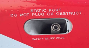
The overboard exhaust valve normally vents warm equipment-cooling air directly overboard on the ground and at low differential pressure. At higher inflight differential pressure it closes and directs that warm air around the forward cargo compartment. On NG YF501–YW164 and MAX aircraft, it opens when either PACK switch is set to HIGH and the right recirculation fan is off.
- Taxi out: outflow valve fully open at low thrust.
- Takeoff: higher thrust commands slight prepressurization for a smoother pressure transition.
- Climb: cabin altitude rises proportionally to aircraft climb.
- Cruise: the controller maintains the lowest cabin altitude permitted by the pressure schedule.
- Descent: the cabin descends toward a point slightly below selected landing altitude.
- Taxi in: the outflow valve slowly opens fully to depressurize the aircraft.
Pressurization panel
The crew enters planned cruise altitude in FLT ALT and destination elevation in LAND ALT. Two identical automatic controllers alternate as primary between flights; the other remains immediately available as backup.
- AUTO: normal automatic controller and DC motor regulate the outflow valve.
- ALTN: the alternate automatic controller regulates pressure after automatic transfer or manual selection.
- MAN: a separate standby-DC-powered motor moves the outflow valve directly through the OPEN/CLOSE switch.
| Selected flight altitude | Maximum scheduled differential pressure |
|---|---|
| At or below 28,000 ft | 7.45 psi |
| 28,000–37,000 ft | 7.80 psi |
| Above 37,000 ft | 8.35 psi |
Failures and warnings
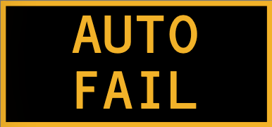
Indicates loss of DC power, a controller fault, an outflow-valve control fault, or an improperly controlled excessive differential pressure, cabin rate or cabin altitude. If the other controller remains available, the system automatically transfers control to it.

Indicates that the alternate automatic controller is operating. With AUTO FAIL, it confirms automatic transfer to single-channel operation.

The aircraft has begun descending before reaching the selected cruise altitude. The controller schedules the cabin back toward takeoff-field elevation unless FLT ALT is changed.

Illuminates green when MAN is selected and the crew directly controls outflow-valve position.
- Cabin altitude warning: an intermittent horn sounds at approximately 10,000 ft cabin altitude.
- Passenger oxygen: masks deploy automatically at approximately 14,000 ft cabin altitude.
- Automatic failure: one failed controller transfers control to the other controller when it remains available; failure of both controllers requires MAN.
Cargo compartments
Both cargo compartments are inside the pressure vessel but have no direct temperature-control zone. Cabin air circulates around their liners and provides indirect heating. The aft outflow path draws cabin air around the aft compartment before discharge.
The forward cargo compartment also receives heat from equipment-cooling exhaust when the overboard exhaust valve is closed. During a forward cargo fire configuration, the valve moves to its smoke position and equipment-cooling airflow is reconfigured to limit smoke migration.