The 737 detects fire or overheat in critical zones and provides dedicated extinguishing or suppression where an airborne response is possible.
- Engines: dual-loop overheat and fire detection, with two shared extinguisher bottles that can be directed to either engine.
- APU: single-loop fire detection and one dedicated extinguisher bottle, controllable from the flight deck or right main wheel well.
- Main wheel well: fire detection only. There is no wheel-well extinguisher and no nose-wheel-well detector.
- Cargo compartments: dual-loop smoke detection and a shared suppression system selectable to the forward or aft compartment.
- Lavatories: local smoke detection plus an automatic, heat-activated extinguisher beneath each sink.
Each engine uses two detector loops for both overheat and fire sensing, while two bottles are shared across both engines.
Engine fire detection
Engine detection is powered by the battery bus. Each engine has two detector loops, A and B. In NORMAL, both loops must normally sense the temperature rise before an alert is generated. If one loop fails, the system automatically deselects it and the remaining loop continues as a single-loop detector without a flight deck indication. An overheat threshold produces the ENG OVERHEAT caution. A higher fire threshold produces the fire warning.
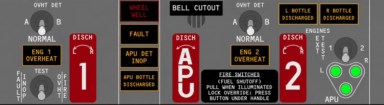
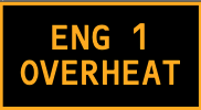
Illuminates amber when the active detection logic senses an overheat condition in the related engine. Both MASTER CAUTION lights and the OVHT/DET system annunciator also illuminate. The light remains illuminated until detector temperature falls below the overheat onset threshold.
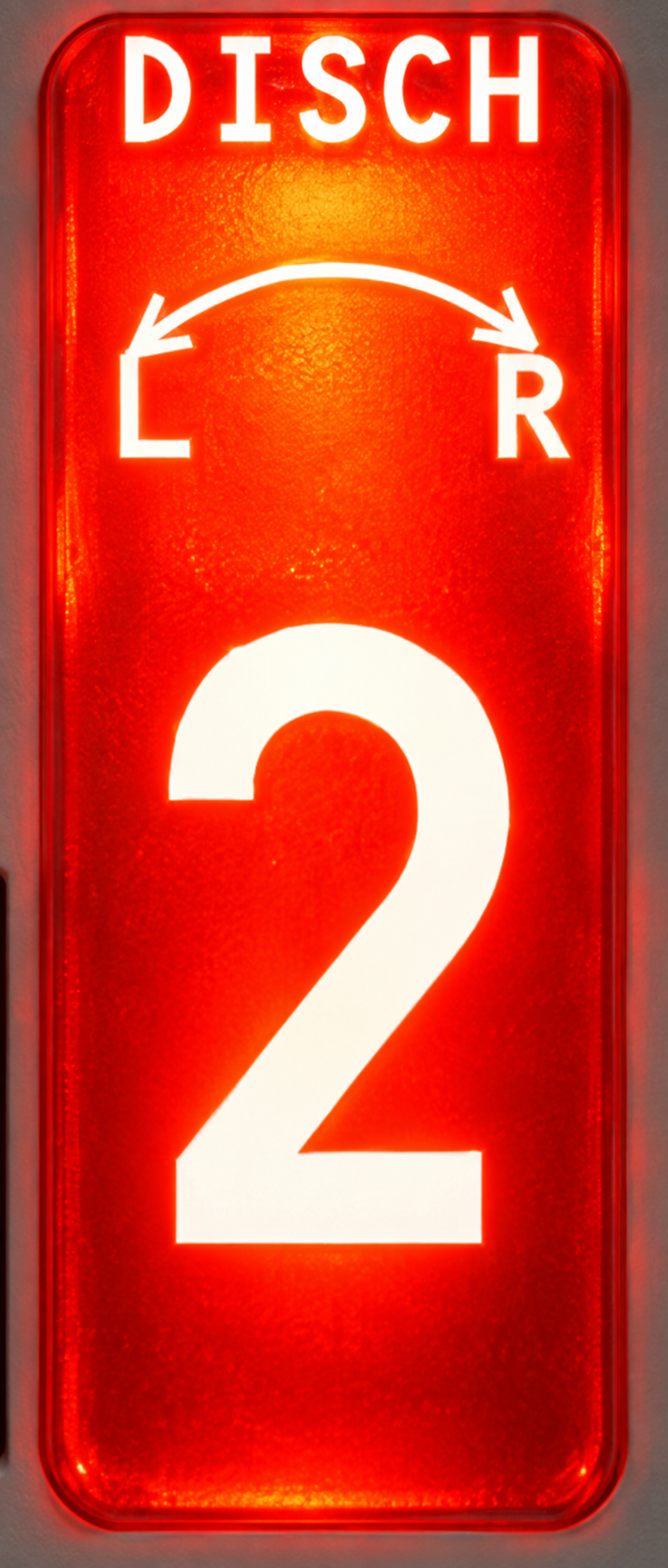
The related engine fire switch illuminates red, the fire warning bell sounds and both master FIRE WARN lights illuminate. The related engine start lever also illuminates where installed, together with all related engine-overheat indications.

In NORMAL, illuminates when both detector loops fail. With A or B selected, it illuminates when the selected loop fails. The OVHT/DET system annunciator and both MASTER CAUTION lights also illuminate.
Go deeper · Detector-loop selection
With the selector in NORMAL, failure of both loops illuminates FAULT and makes detection for that engine inoperative. Selecting A or B makes the system operate from that loop alone; the non-selected loop is not monitored, and failure of the selected loop illuminates FAULT.
Engine fire extinguisher
The hot battery bus powers the extinguishing system, so it remains available independently of the normal electrical configuration. Either bottle can be discharged into either engine.
Pulling the illuminated engine fire switch isolates the affected engine by closing the engine and spar fuel shutoff valves, engine bleed valve and hydraulic fluid shutoff valve. It trips the generator, disables the related thrust reverser and arms one squib on each bottle. Rotating the switch discharges one bottle; rotating it the opposite way discharges the remaining bottle.
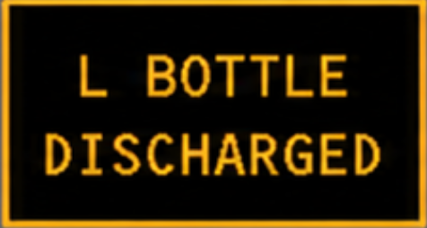
Illuminates amber a few seconds after the related extinguisher bottle is discharged. It also illuminates if pressure in that bottle is low.
Fire test
FAULT/INOP test: hold the FAULT/INOP and OVHT/FIRE TEST switch at FAULT/INOP to check the engine and APU fault-monitoring circuits.
- Both MASTER CAUTION lights illuminate.
- The OVHT/DET system annunciator illuminates.
- The amber FAULT light illuminates.
- The amber APU DET INOP light illuminates.
OVHT/FIRE test: hold the switch at OVHT/FIRE to check the engine overheat/fire loops, APU fire loop and main-wheel-well detector.
- The fire warning bell sounds.
- Both master FIRE WARN lights illuminate.
- Both MASTER CAUTION lights and the OVHT/DET annunciator illuminate.
- Both engine fire switches and both ENG OVERHEAT lights illuminate.
- The APU fire switch illuminates.
- Both engine start levers illuminate where installed.
- With AC power available, the WHEEL WELL light illuminates.
- On the ground, the wheel-well APU horn sounds and its APU fire warning light flashes.
The APU combines one fire loop, automatic shutdown logic and a dedicated bottle available from both flight deck and ground controls.
APU fire detection
A single battery-bus-powered loop detects an APU fire; there is no separate APU overheat threshold. A loop failure illuminates APU DET INOP. An APU fire sounds the fire bell, illuminates both master FIRE WARN lights and the APU fire switch, and automatically shuts down the APU.
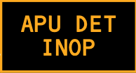
Illuminates amber when the single APU detector loop has failed. The APU fire-detection system is then inoperative; both MASTER CAUTION lights and OVHT/DET also illuminate.
On the ground, the horn sounds and the red APU fire warning light flashes in the right main wheel well so ground personnel receive the warning without flight deck access.
APU fire extinguisher
One bottle is powered by the hot battery bus. Pulling the APU fire switch backs up the automatic shutdown, closes the fuel shutoff valve, bleed valve and inlet door, trips the generator, and arms the extinguisher squib. Rotating the switch in either direction discharges the bottle.
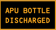
Illuminates amber a few seconds after the APU extinguisher bottle is discharged. It also illuminates if bottle pressure is low.
APU ground control
The ground control panel in the right main wheel well allows ground personnel to respond without entering the flight deck.
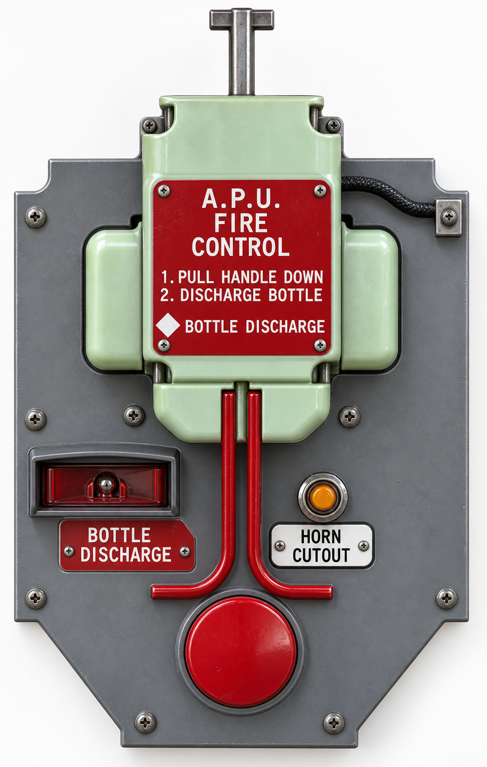
- Fire control handle — pull down: arms the local bottle-discharge switch, closes the APU fuel shutoff and bleed-air valves, closes the APU inlet door, and trips the generator control relay and breaker.
- BOTTLE DISCHARGE — move left: discharges the APU extinguisher, provided the local fire-control handle has first been pulled.
- HORN CUTOUT — push: silences the fire bell and wheel-well horn; the red APU fire light stops flashing and remains steadily illuminated.
The main wheel well is monitored for fire, but the aircraft carries no extinguishing system for this zone.
The detector is powered by AC transfer bus 2 and the battery bus. A detected fire sounds the fire bell, illuminates both master FIRE WARN lights and illuminates the red WHEEL WELL light. The warning remains until detector temperature falls below its onset threshold.

Illuminates red when the main-wheel-well detector senses a fire. The fire warning bell sounds and both master FIRE WARN lights illuminate. The light remains illuminated until detector temperature falls below the onset threshold.
Smoke detectors identify the affected compartment and a shared bottle system suppresses the fire throughout the diversion.
Cargo fire detection
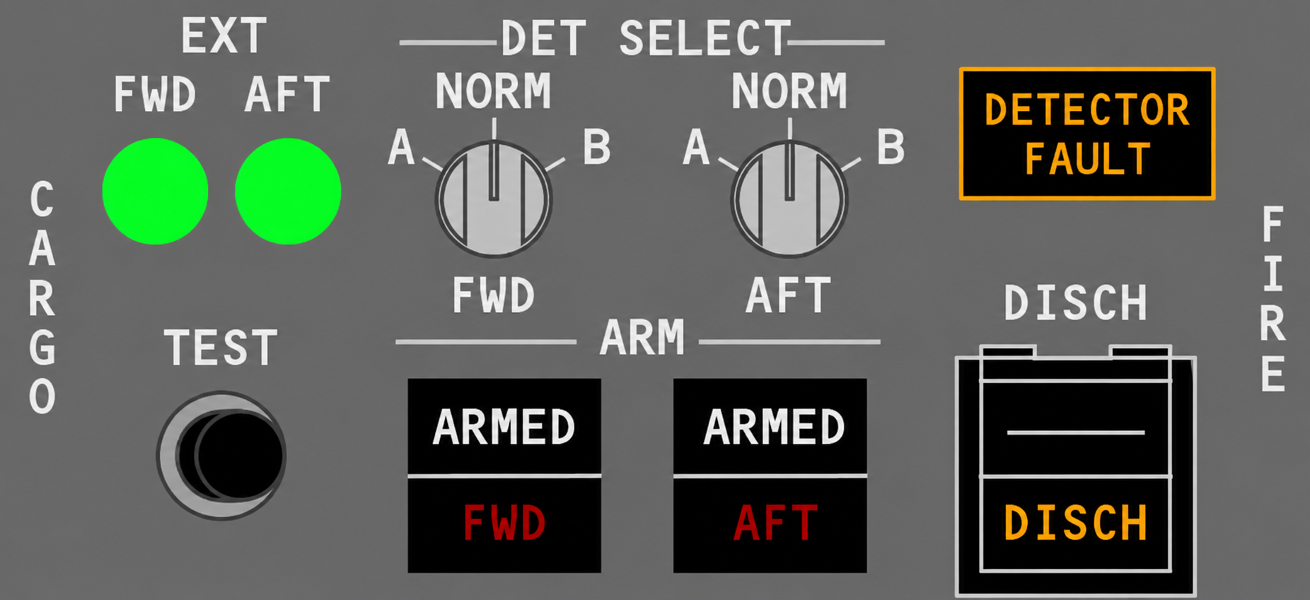
DC buses 1 and 2 power dual-loop smoke detection in both forward and aft cargo compartments. Both loops normally must sense smoke. Loss of power to one loop converts the system automatically to single-loop detection. A detector failure can be handled manually with the DET SELECT switch.
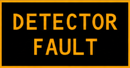
Illuminates amber when one or more detectors in a selected loop has failed in either cargo compartment. Pressing the light tests its bulbs. Cargo-panel cautions are not connected to MASTER CAUTION.
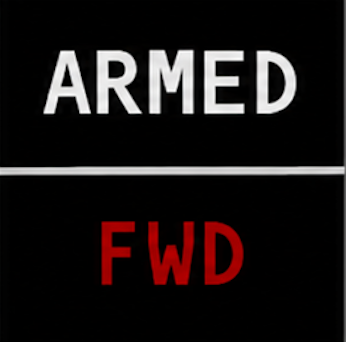
The lower red FWD or AFT light illuminates when the selected detector logic senses smoke in that compartment. The fire bell sounds and both master FIRE WARN lights illuminate. The upper white ARMED light confirms that the extinguisher has been armed for the selected compartment.
Cargo fire suppression
Pushing the appropriate FWD or AFT ARMED switch selects the compartment and arms its discharge path. Pushing DISCH releases the extinguishing agent. The DISCH light may take up to 30 seconds to illuminate.
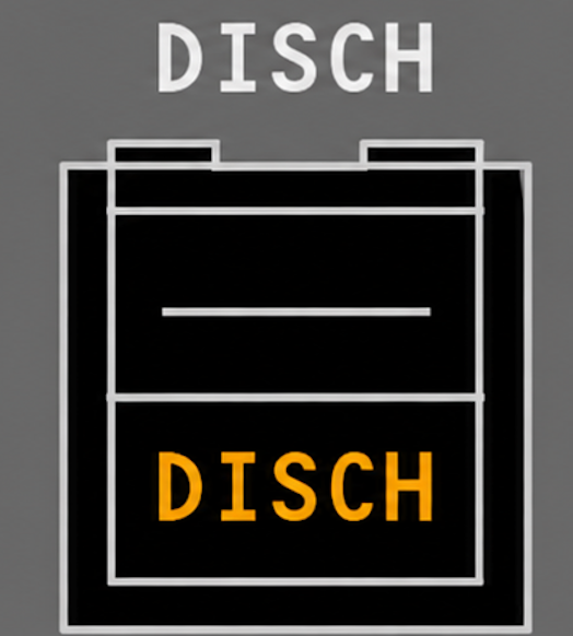
With a compartment armed, press the switch for at least one second to discharge the first or only extinguisher bottle and start the applicable second-bottle timer. The lower amber DISCH light indicates that a bottle has discharged or its pressure is low.
Go deeper · Why the warning can return
Cargo detectors sense airborne particles and cannot distinguish smoke from suppression agent. A re-illuminated FWD or AFT light after discharge does not, by itself, prove that suppression has failed.
Each lavatory has local smoke warning and automatic protection for the waste-bin area beneath the sink.
Smoke detection
When the lavatory detector senses smoke, a local aural warning sounds and a red alarm or status light illuminates on the detector panel. There is no flight deck indication. Depending on the installed detector, the alarm is silenced locally and resets automatically, or is reset with the INTERRUPT switch once smoke is no longer present.
Extinguisher
A dedicated extinguisher is installed beneath the sink in each lavatory. Heat activates it automatically and directs extinguishing agent toward the waste container. The flight deck receives no indication that the bottle has discharged.